
Multiple lamp illumination system with polarization recovery and integration

a multi-lamp, illumination system technology, applied in the direction of instruments, lighting support devices, polarising elements, etc., can solve the problems of increasing cost and space requirements, insufficient means for uniform illumination and polarization recovery, etc., and achieve the effect of high brightness uniform illumination

Inactive Publication Date: 2010-05-18
THOMSON LICENSING SA
View PDF6 Cites 3 Cited by
  • Summary
  • Abstract
  • Description
  • Claims
  • Application Information

AI Technical Summary

Benefits of technology

The present invention provides an illumination system that combines multiple light sources to create a high brightness, uniform illumination. The system includes a light pipe system with multiple collecting light pipes and a combining light pipe. Each collecting light pipe has a polarizing beam splitter and a mirror, which direct the light from the light sources towards the combining light pipe. The combining light pipe collects and combines the light from each polarizing beam splitter and mirror. The technical effect of this invention is a more efficient and effective use of multiple light sources to create a uniform and bright illumination.

Problems solved by technology

In existing light projection systems there is typically a tradeoff between optimum brightness and lamp life.
However, when such systems which are adapted for use with microdisplays, there is not adequate means for uniform illumination and polarization recovery.
These systems are also limited to two lamps, and require two relay lenses increasing cost and space requirements.

Method used


Image

  • Multiple lamp illumination system with polarization recovery and integration
  • Multiple lamp illumination system with polarization recovery and integration
  • Multiple lamp illumination system with polarization recovery and integration

Examples


Embodiment Construction

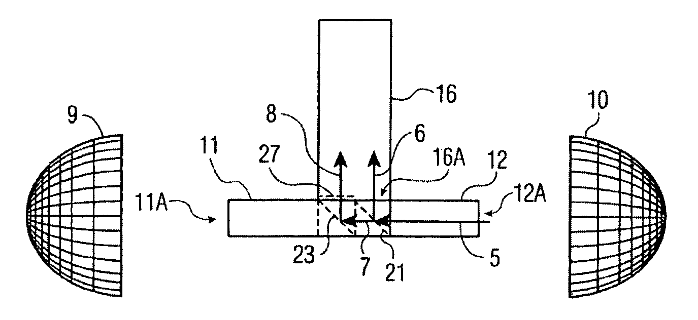
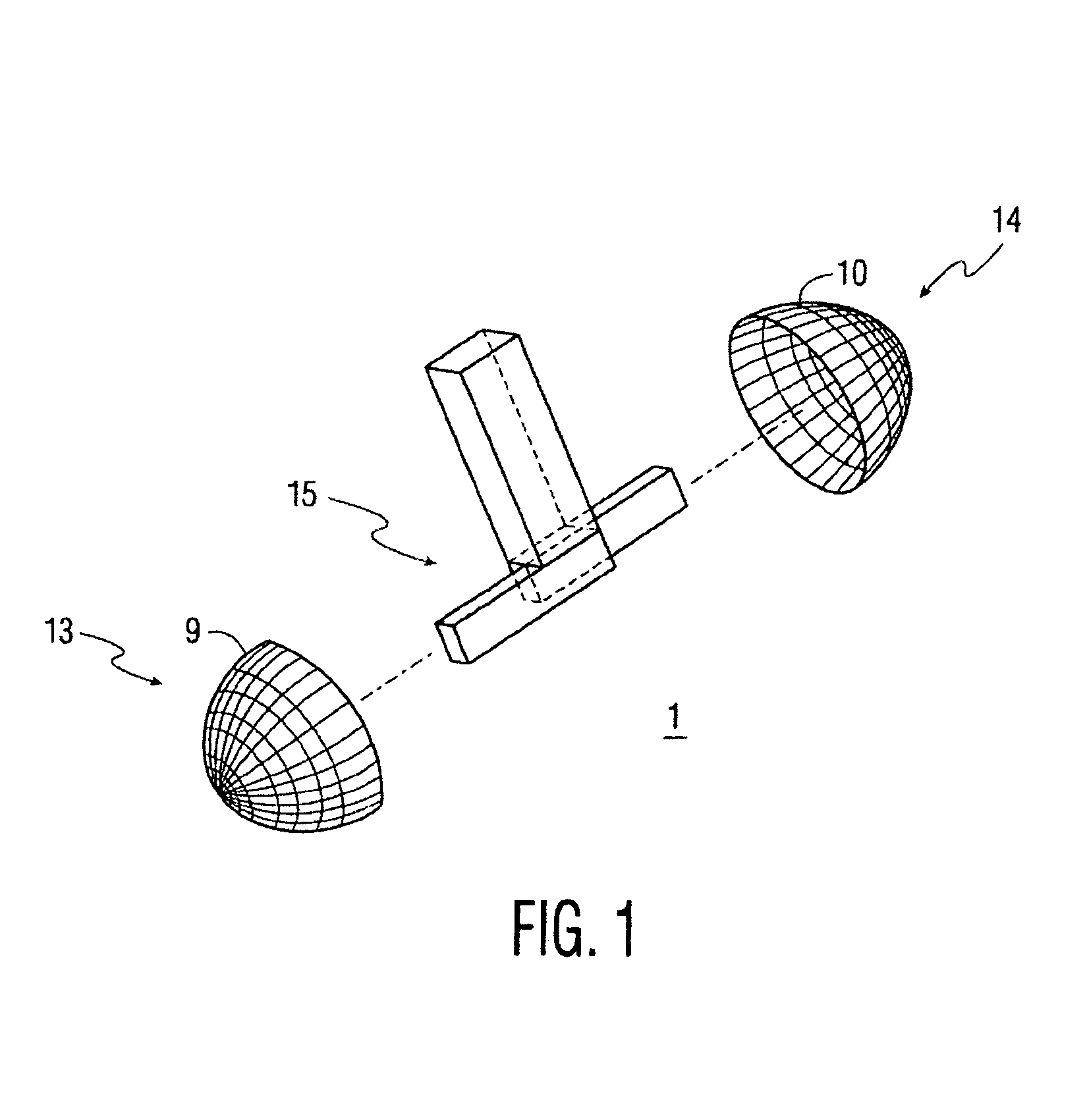
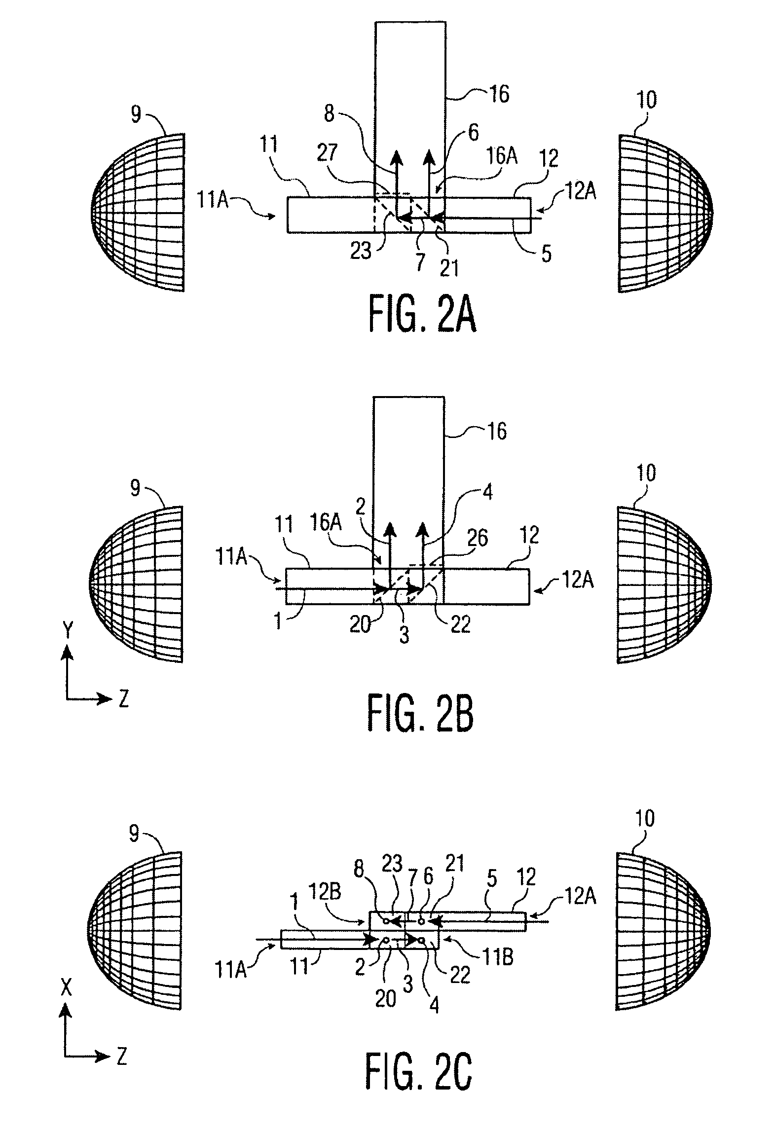
[0008]In applications requiring a very high brightness, like for example, digital cinema, it may be desirable to use more than one lamp in the illumination system for significantly boosting the light throughput. This disclosure describes such an architecture that has also the advantage of recovering the polarization and integrating the light beam for delivering a high brightness uniform illumination. Moreover, this system requires a reduced number of lenses for low cost and also for making the system more compact.

[0009]FIGS. 1-2C show a dual lamp system 1, however the following discussion is also applicable to a four lamp system. In the dual lamp scheme, a burner (not shown) is set into a light-collector / light-reflector 9, 10 for each of two oppositely directed lamps 13, 14 with a light pipe system 15 disposed between the lamps 13, 14. An elliptical reflector is well suited as a collector, but the collecting means could be different. There is a collecting lightpipe 11, 12 having an ...


PUM

PropertyMeasurementUnit
aspect ratioaaaaaaaaaa
areaaaaaaaaaaa
areasaaaaaaaaaa

Abstract

An illumination system is provided for combining two or more light sources. A plurality of light sources radiate random polarization light. A plurality of collecting light pipes corresponds to the plurality of light sources. Each collecting light pipe has an entrance end disposed towards the respective light source. The collecting light pipes are laterally offset and overlapping opposite their respective entrance ends. A combining light pipe is disposed perpendicular to the collecting light pipes. A polarizing beam splitter and a mirror are sequentially arranged in each collecting light pipe essentially opposite the entrance end directing a first polarization light and a second polarization light, respectively upwards towards the combining light pipe. The combining light pipe has an entrance end overlying the polarizing beam splitter and mirror of each collecting light pipe to collect and combine the light from each polarizing beam splitter and mirror.

Description

CROSS-REFERENCE TO RELATED APPLICATIONS[0001]This application claims the benefit, under 35 U.S.C. §365 of International Application PCT / EP2005 / 051093, filed Mar. 10, 2005, which was published in accordance with PCT Article 21(2) on Sep. 22, 2005 in English and which claims the benefit of U.S. provisional patent application No. 60 / 552,284, filed Mar. 11, 2004.FIELD OF THE INVENTION[0002]The invention relates generally to a light projection system for use with a microdisplay.BACKGROUND OF THE INVENTION[0003]In existing light projection systems there is typically a tradeoff between optimum brightness and lamp life. One approach to this problem is to provide a system with two lamps. However, when such systems which are adapted for use with microdisplays, there is not adequate means for uniform illumination and polarization recovery. These systems are also limited to two lamps, and require two relay lenses increasing cost and space requirements.SUMMARY[0004]According to an exemplary embo...

Claims


Application Information

Patent Timeline
Patent Type & Authority Patents(United States)
IPC IPC(8): F21V9/14F21V8/00G02B6/28G02B6/42G02F1/13357
CPCG02B6/2817G02B6/4298G02B6/4214G02B6/00G02B6/0001
Inventor DRAZIC, VALTER
Owner THOMSON LICENSING SA
Learn More