Applicator device for suppositories and the like

a technology for suppositories and applicators, which is applied in the field of applicator devices for suppositories, can solve the problems of difficult expulsion of same from applicators, and achieve the effect of facilitating the release of pharmaceutical products

Inactive Publication Date: 2010-05-18
JOHNSON & JOHNSON CONSUMER COPANIES
View PDF59 Cites 839 Cited by
  • Summary
  • Abstract
  • Description
  • Claims
  • Application Information

AI Technical Summary

Problems solved by technology

As a result, when the suppositories stick to the applicators during storage or use, it becomes difficult to expel same from the applicators.

Method used


Image

  • Applicator device for suppositories and the like
  • Applicator device for suppositories and the like
  • Applicator device for suppositories and the like

Examples


first embodiment

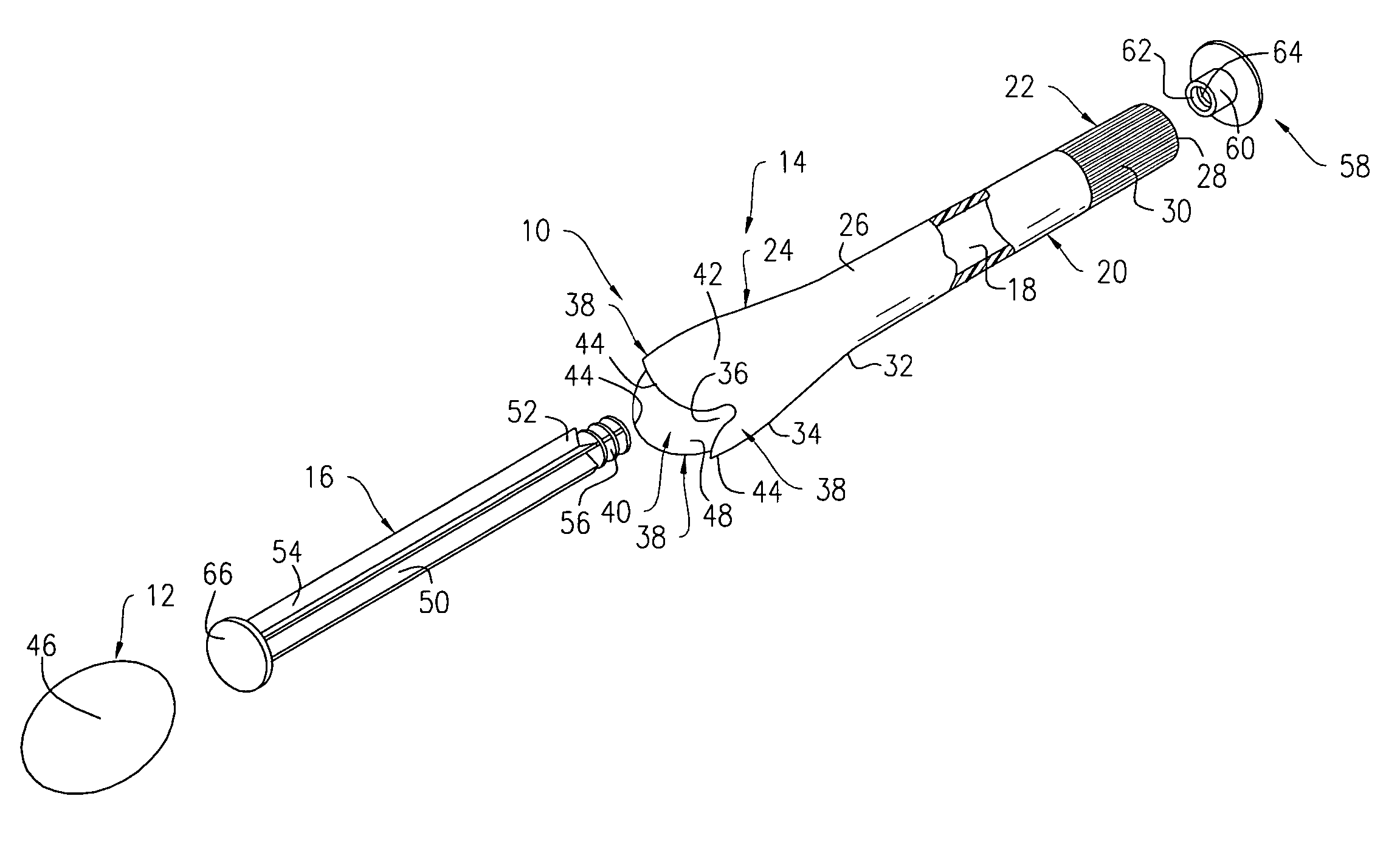
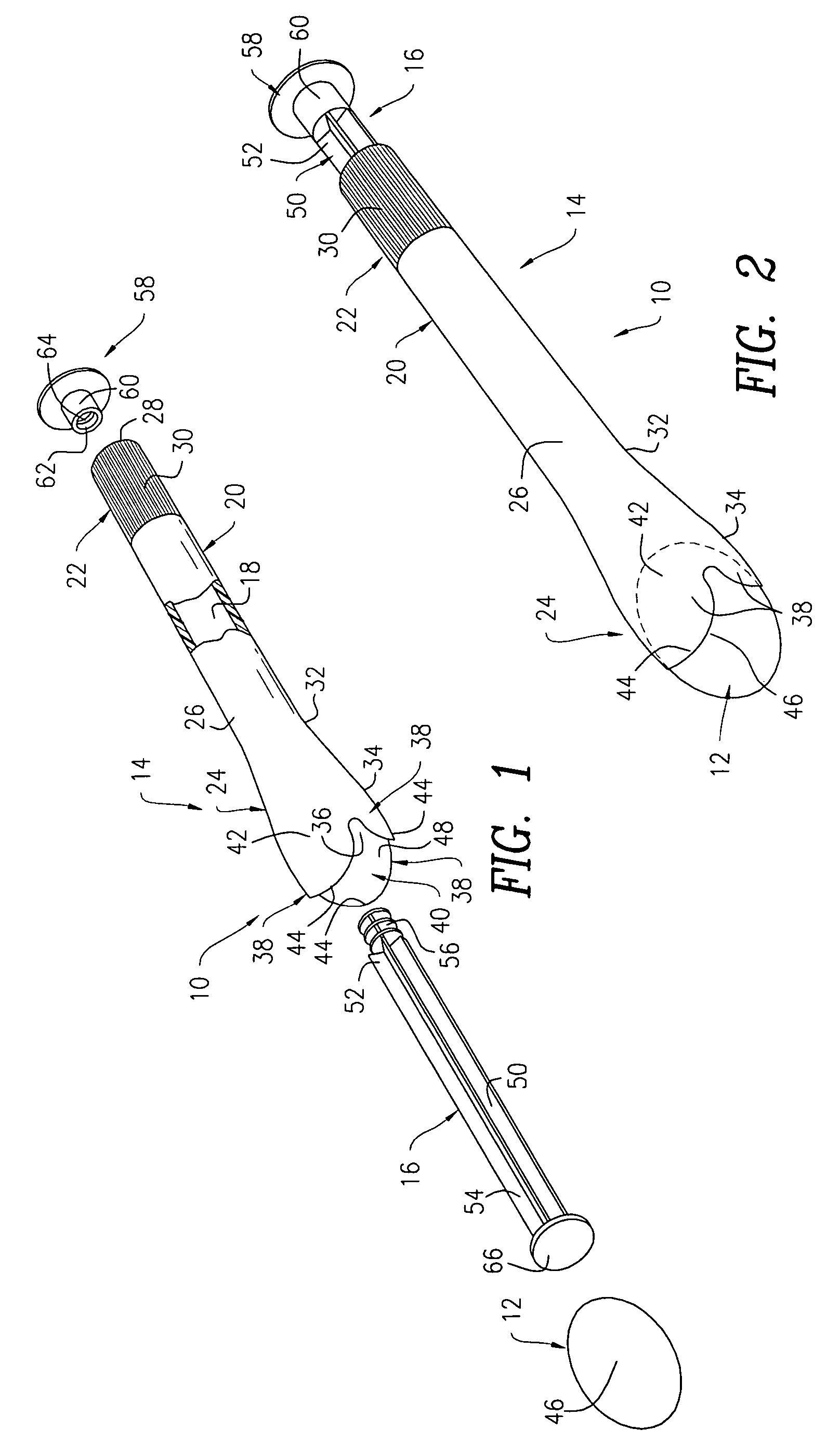
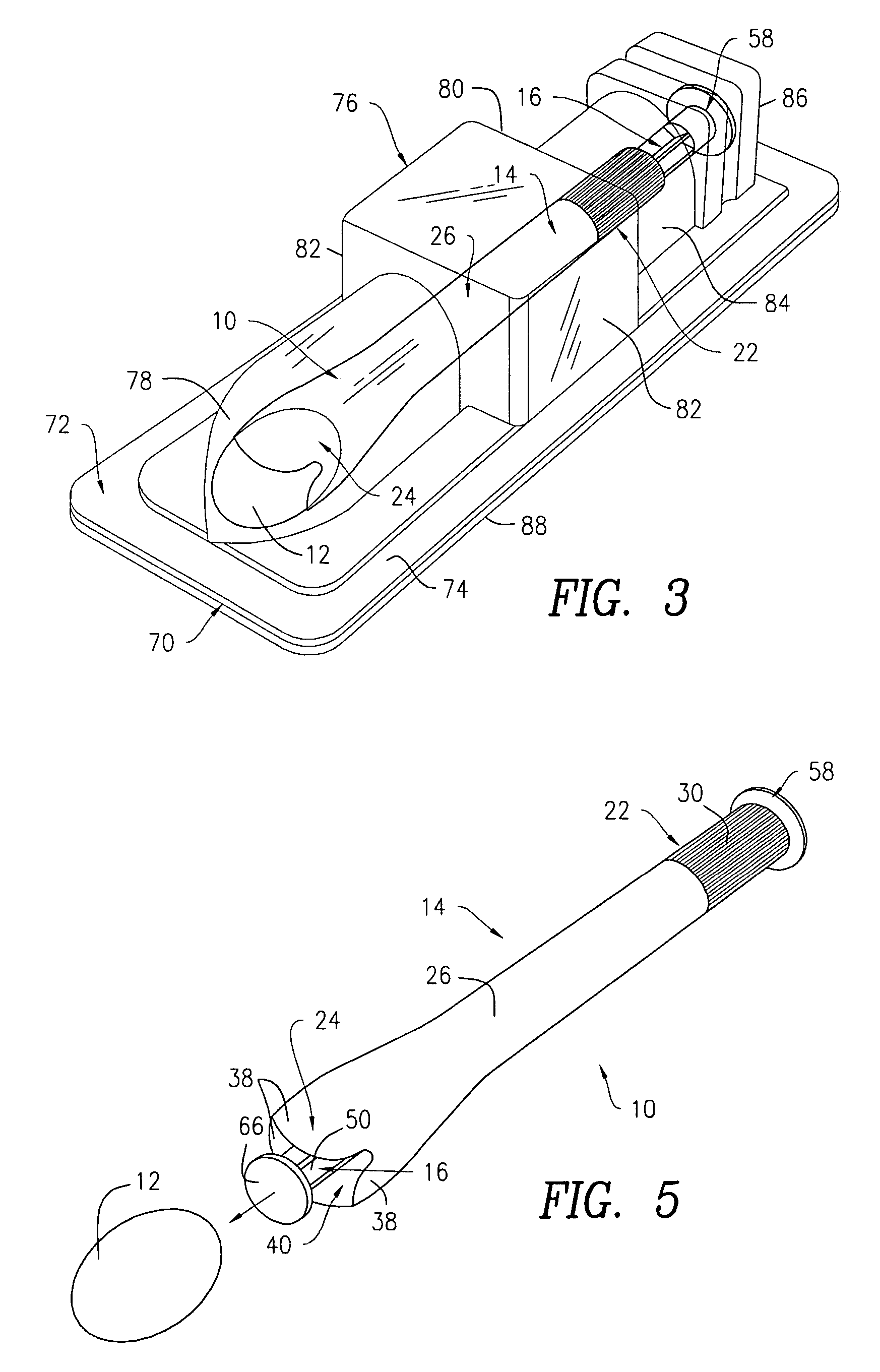
[0018]Referring to FIGS. 1, 2 and 5, there is shown a suppository applicator 10 constructed in accordance with the present invention. More particularly, the applicator 10 is adapted for use in depositing an oval-shaped suppository product 12 in a bodily cavity, such as a vaginal cavity, a rectum, etc. The applicator 10 includes a barrel member 14 and a plunger member 16 extending through the barrel member 14. The barrel member 14 and the plunger member 16 are made from a suitable material (e.g., thermoplastics, polyolefins, polyolefin copolymers, modified polyvinyl chloride, thermoplastic rubber compounds, polyurethanes, etc.) preferably by a conventional injection molding process. Alternatively, one or both of the barrel member 14 and the plunger member 16 can be made by using other conventional processes.

[0019]Now referring to FIGS. 1, 2 and 5-7, the barrel member 14 is provided with an interior passageway 18 extending therethrough. The barrel member 14, which has a unitary constr...

second embodiment

[0035]With reference to FIGS. 8, 9, 12 and 13, there is shown a suppository applicator 110 constructed in accordance with the present invention. The applicator 110, which is adapted for use in delivering an oval-shaped suppository product 112 to a bodily cavity (e.g., a vaginal orifice), includes a barrel member 114 having an open proximal end 128 and an open distal end 134. Unlike the barrel member 14 of the embodiment of FIGS. 1-7, the entire barrel member 114 is substantially cylindrical in shape and is slightly tapered as it extends from the proximal end 128 to the distal end 134 (i.e., the diameter of the proximal end 128 is slightly greater than that of the distal end 134). As a result, the distal end 134 of the barrel member 114 is not flared. The barrel member 114 includes an interior passageway 118 extending between the proximal and distal ends 128, 134. A perimeter rim wall 190 is formed at the proximal end 128, while first restricting means, such as an annular retaining r...


PUM


Abstract

An applicator for delivering pharmaceutical products or the like to a bodily cavity includes a barrel member having a distal end which is equipped with an opening. The applicator also includes a plurality of petals extending outwardly from the distal end in a generally axial direction. The petals cooperate with the opening so as to form a receptacle for releasably receiving a pharmaceutical product in the distal end of the barrel member. Each of the petals has a truncated flexible tip sized and shaped so as to engage a substantially central portion of the pharmaceutical product such that a large section of the pharmaceutical product extends outwardly beyond the petals so as to facilitate the release of the pharmaceutical product from the receptacle. The device also includes a plunger member for releasing the pharmaceutical product from the receptacle. In accordance with the present invention, the device can be packaged in a package together with the pharmaceutical product received in the receptacle.

Description

CROSS-REFERENCE TO RELATED APPLICATIONS[0001]This is a divisional of U.S. patent application Ser. No. 10 / 366,710, filed Feb. 12, 2003 now U.S. Pat. No. 7,198,612 which is a continuation-in-part of U.S. patent application Ser. No. 10 / 172,729, filed Jun. 14, 2002, now U.S. Pat. No. 7,104,968. The disclosures of U.S. patent application Ser. Nos. 10 / 172,729 and 10 / 366,710 are incorporated herein by reference in their entirety.FIELD OF THE INVENTION[0002]The present invention relates to applicator devices for suppositories and the like and, more particularly, to an applicator device adapted for depositing suppositories and the like in a bodily cavity or passage.BACKGROUND OF THE INVENTION[0003]Suppository applicators have been in use for delivering suppositories to bodily cavities, such as vaginal canals and recta. Conventional applicators are equipped with barrel members for receiving suppositories and plunger members for expelling same from the barrel members. The barrel members have l...

Claims


Application Information

Patent Timeline
Patent Type & Authority Patents(United States)
IPC IPC(8): A61M31/00A61F13/20A61M3/00
CPCA61M31/007A61M25/002
Inventor SWICK, PAUL B.
Owner JOHNSON & JOHNSON CONSUMER COPANIES
Why Eureka
Try Eureka