X-ray fluorescence apparatus

a fluorescence apparatus and x-ray technology, applied in the field of xray fluorescence, can solve the problems that the use of an energy-resolving solid-state detector in combination with an analyzer crystal does not deliver any benefit, and achieve the effect of reducing the background and facilitating the detection of small peaks

Active Publication Date: 2010-05-18
PANALYTICAL BV
View PDF10 Cites 7 Cited by
  • Summary
  • Abstract
  • Description
  • Claims
  • Application Information

AI Technical Summary

Benefits of technology

[0013]However, the combination of crystal and energy-resolving detector does give rise to unexpected benefits.
[0021]By using an energy resolving detector, it is possible to correct for the scattered radiation background since it is at a different energy to the energy being measured. This removes this component and hence reduces the background. This makes it easier to detect small peaks in the XRF spectrum which is very useful for trace analysis.

Problems solved by technology

It might at first be thought that using an energy-resolving solid state detector in combination with an analyzer crystal does not deliver any benefit, since the analyzer crystal effectively selects a particular energy and so the detector does not receive multiple energies simultaneously.

Method used


Image

  • X-ray fluorescence apparatus
  • X-ray fluorescence apparatus
  • X-ray fluorescence apparatus

Examples


Embodiment Construction

[0038]The Figures are schematic and not to scale. Like or similar components are given the same reference numerals in the different Figures.

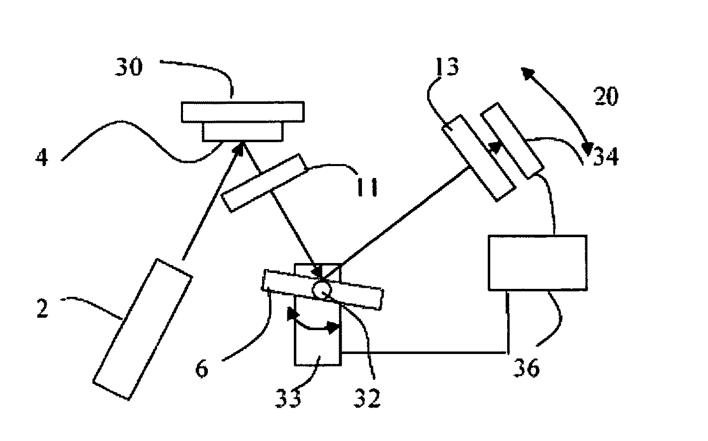
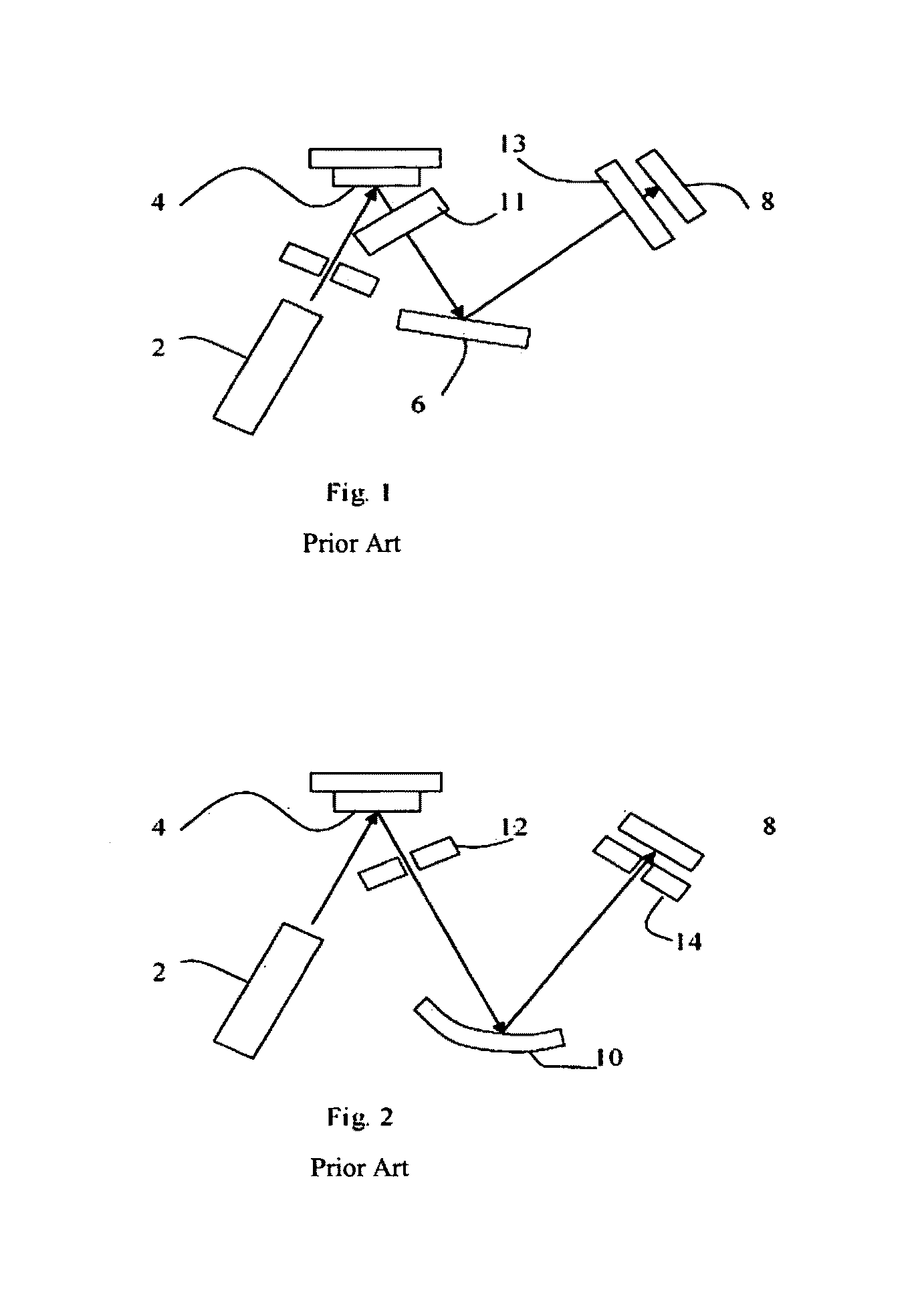
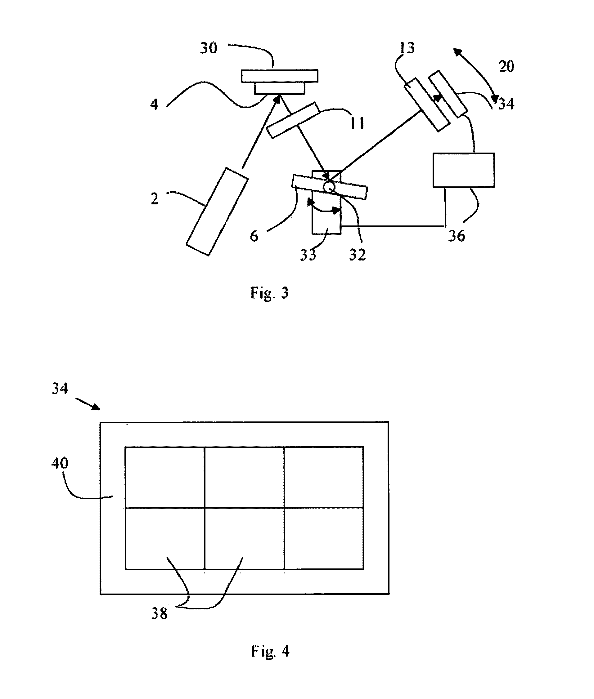
[0039]Referring to FIG. 3, a WDXRF application according to the invention includes a X-ray source 2, a sample stage 30 for holding a sample 4, and a flat single analyzer crystal 6 mounted on a goniometer axis 32 for rotation about the axis by drive means 33. The analyzer crystal may be of LiF, PE, TlAP, InSb, Ge, for example or a multilayer of W / Si, Mo / B4C, Ni / C, Cr / C, Fe / Sc or La / B4C for example. A primary collimator 11 and a secondary collimator 13 direct X-rays from the sample to the detector, the X-rays being reflected by the analyzer crystal. Note that the collimators are shown schematically and in practice any suitable form of collimator may be used.

[0040]Unlike the arrangement of FIG. 1, the detector in this case is a silicon drift detector (SDD) 34 that measures the intensity of radiation as a function of energy.

[0041]The detector 34 and...


PUM

PropertyMeasurementUnit
aaaaaaaaaa
energyaaaaaaaaaa
θ-aaaaaaaaaa

Abstract

An X-ray fluorescence (XRF) apparatus uses both an analyzer crystal (6) and a silicon drift detector (34). By using this combination problems of background and overlapping peaks can be mitigated.

Description

CROSS-REFERENCE TO RELATED APPLICATIONS[0001]This application claims priority under 35 U.S.C. §119(a)-(d) or (f), or 365(b) to European Community, Application No. 07105796.2, filed Apr. 5, 2007, the entire contents of which are incorporated herein by reference.TECHNICAL FIELD[0002]The invention relates to X-ray fluorescence (XRF), and to an apparatus that uses XRF.BACKGROUND[0003]XRF is a well known technique for measuring properties of samples. A number of different configurations are known.[0004]In wavelength dispersive XRF (WDXRF), X-rays from an X-ray source are incident onto a sample. These cause X-ray fluorescence, i.e. X-rays emitted at a range of energies that act as a signature of the sample material. In a first arrangement, illustrated in FIG. 1, X-rays are emitted by tube 2 as the source and then are incident on sample 4. The X-rays from the sample are incident on a flat analyzer crystal 6 which diffracts them according to the Bragg equation onto a detector 8. By moving t...

Claims


Application Information

Patent Timeline
Patent Type & Authority Patents(United States)
IPC IPC(8): G01N23/223
CPCG01N23/223G01N2223/076
Inventor HEGEMAN, PETRABRONS, CHRISTIANBROUWER, PETER
Owner PANALYTICAL BV
Why Eureka
Try Eureka