Egg vaccination apparatus

a technology of egg and ovule, which is applied in the field of egg vaccination apparatus, can solve the problems of injuring operators, damage to vaccine cells, and pressure within the air bladder, and achieve the effect of rapid and uniform inflation

Active Publication Date: 2010-05-25
MERIAL INC
View PDF27 Cites 33 Cited by
  • Summary
  • Abstract
  • Description
  • Claims
  • Application Information

AI Technical Summary

Benefits of technology

[0018]In certain embodiments the present invention features large diameter longitudinal air tubes that are inserted into the injector alignment plate, the plate which is located closest to the eggs, with one air tube placed between each row of injectors. These air tubes have at least two high-pressure pneumatic air valves that rapidly inject large quantities of compressed air, filling the air tubes quickly and applying pressure to large surface areas of the lower portion of the injectors. The location of the air tube is critical to its ability to secure the injectors firmly in place. The closer the tubes are to the point of contact with the eggs, the less mobility is possible. Because of the relative large size of the air bag in the preferred embodiment, the injectors are held in a rigid position when in contact with the egg, minimizing the possibility of vertical or lateral movement. With the injector thus secured and the injector alignment plate being firmly fixed to the machine, there is a reduced possibility of vibrations being passed from the injector to the egg at time of penetration.
[0019]The present invention presented herein has in a preferred embodiment an injector alignment plate and an independent injector support plate that can be exchanged for plates for different sizes and configurations to be used in the same vaccinator. Utilizing the two independent components, one to lift and lower the injectors and the other to guide and secure the injectors, changing the components is an easy task. This operation takes less than ten minutes and does not disrupt the in-egg vaccination process. The present invention will save investment in equipment over the device taught by the '979 patent, which requires two machines if two different types of egg flats are being utilized.
[0020]The present invention further, in a preferred embodiment, has an injector support plate independent of the injector alignment plate that permits the use of an injector that has an electronic sensor embedded in the cap, which rests on the injector support plate in its normal raised position. When the injector support is lowered over the eggs, the injector cap is raised by the egg through the hole in the injector support plate. If for any reason, such as infertile eggs removed during candling, there is an empty space in the egg flat, the injector does not lift up from the injector support plate. An electronic sensor embedded into the injector cap then sends an electronic signal to the microprocessor, which inhibits the injector from injecting vaccine into the empty space. The saving of vaccine by not injecting into empty spaces represents a cost savings, since infertile and dead embryos average 7 to 10% of the eggs being vaccinated.
[0021]Further in the preferred embodiment of the present invention, having two independent and easily removable plates, the injector support plate and the injector alignment plate, separate from one another makes injector sanitization much more efficient. With the injector support plate being-separate and removable from the injector alignment plate it is a simple matter to sanitize between the two independent plates.
[0023]With the injector alignment plate firmly in its position, the injector support plate with the injectors is lowered by the air cylinders of a preferred embodiment of the present invention until the injectors pass through the corresponding holes in the alignment plate. The holes in the injector alignment plate are larger in diameter than the holes in the injector support plate to allow a 360-degree lateral movement of the injectors within the injector alignment plate. Inside the injector alignment plate, parallel to each row of injectors, there are large diameter cylindrical pneumatic air tubes made of an expandable polymer material that when deflated allow the free passage of the injector through the injector alignment plate holes. When the injectors are lowered into place above the eggs, high-pressure compressed air is injected through high-speed, large-capacity pneumatic valves into each air bag at two or more air connections located in the tubes to insure rapid uniform inflation.
[0024]The air tubes inflated from both ends become rigid structures, pressing firmly against the injectors on either side to insure that the injectors are immobilized. The positioning of these air tubes inside the injector alignment plate is very important to the integrity of the eggs since the injectors are being secured at the point just above the needle exit, allowing no play in the injectors as the needles makes contact with the eggshell. The position of the air tubes in the injector alignment plate at the point of the injector closest to the egg insures that the injector will suffer the least possible lateral movement at the moment of impact of the injection needle into the egg.

Problems solved by technology

However, the pressure is within the air bladder which would rip if there were some damage to its structure or at worst explode to release the air without propelling hard acrylic material which could injure operators.
The system guarantees that the vaccine line pressure never surpasses 5 psi, which could damage vaccine cells and reduce the quality of vaccination.

Method used


Image

  • Egg vaccination apparatus
  • Egg vaccination apparatus
  • Egg vaccination apparatus

Examples


Embodiment Construction

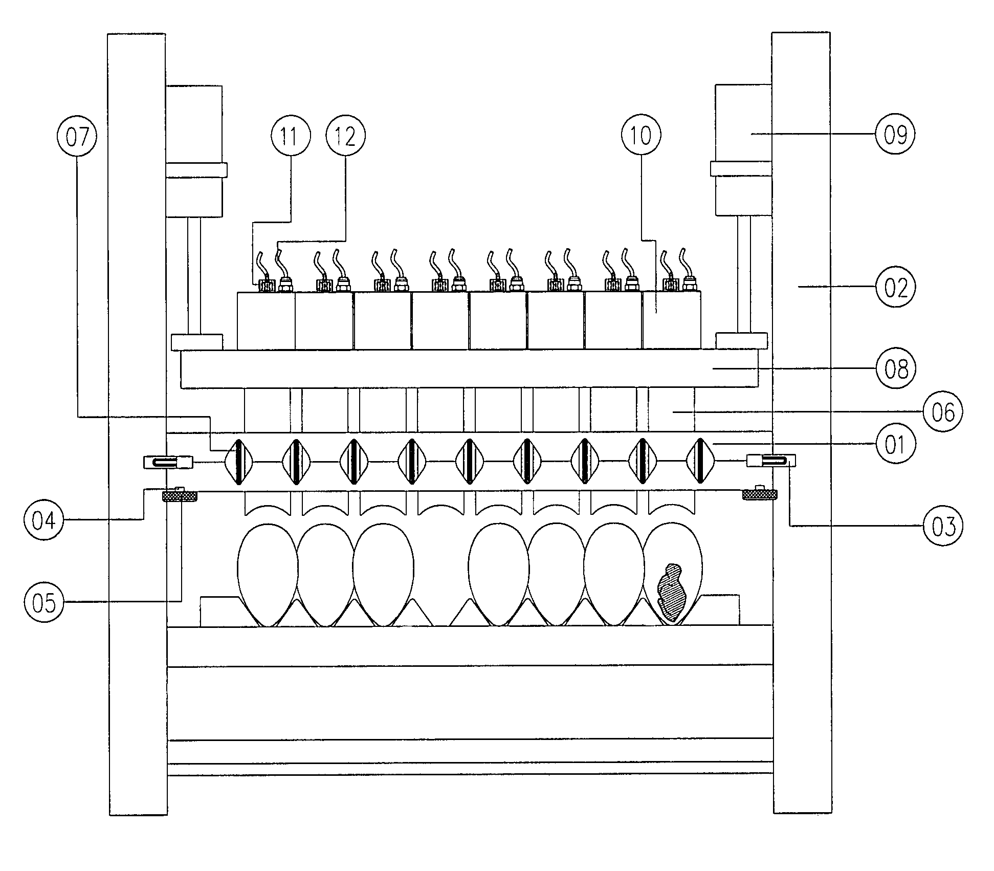
[0035]With reference now to FIGS. 1-9, detailed explanations of the preferred embodiment of the present invention will be given. The purpose of the drawings is to further the explanation of the preferred embodiment, without limiting the scope of the invention as claimed herein.

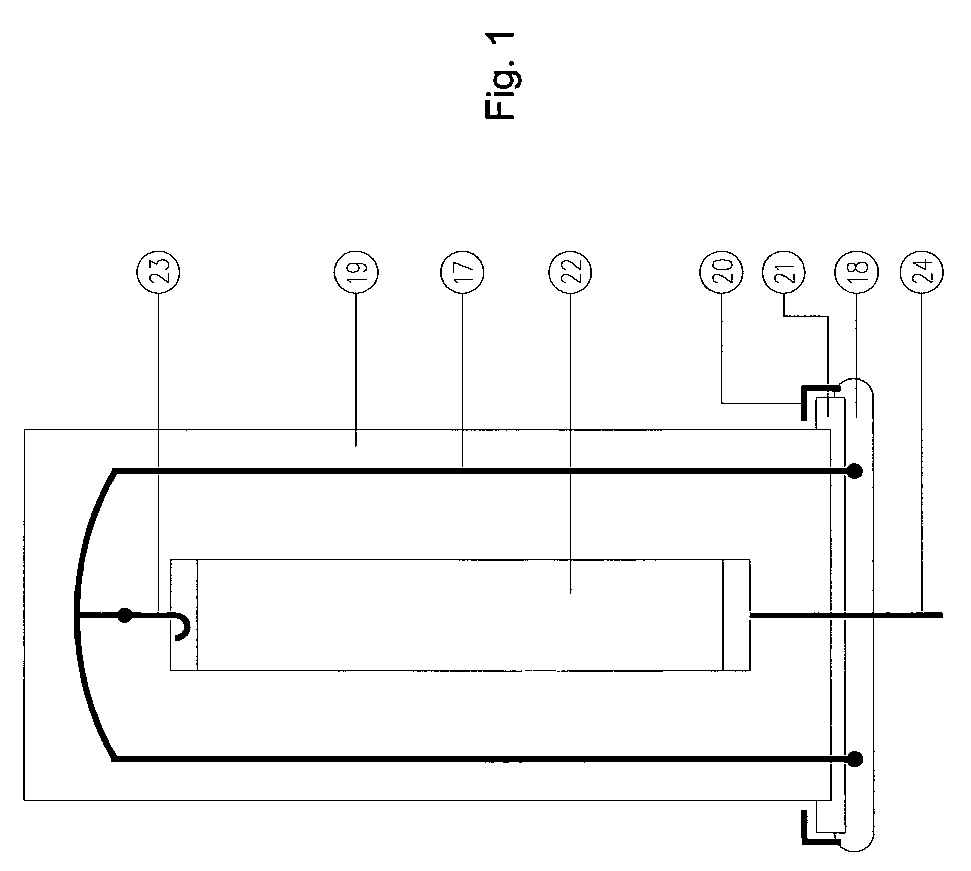
[0036]FIG. 1 shows the vaccine chamber before beginning the vaccination process with the “U” support 17 affixed to the aluminum base of the chamber 18 and the acrylic top 19 filled over the “U” support with quick connect fasteners 20 fitting over the lip of the chamber 21 and the air bag 22 suspended from one of the three “U” support hooks 23. The air bag feed line 24 passes through the base of the chamber.

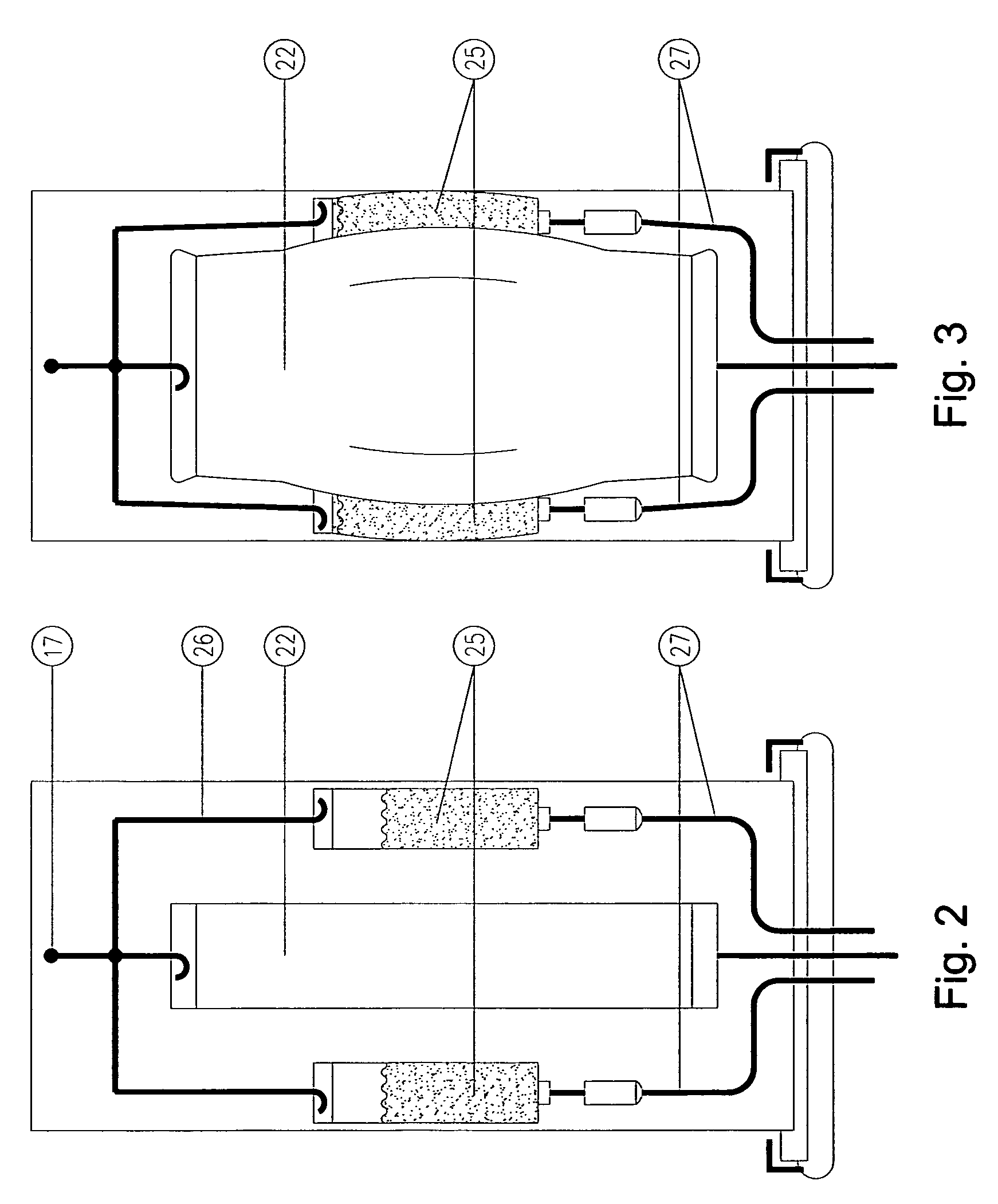
[0037]FIG. 2 shows the vaccine chamber rotated 90° to show the two full vaccine bags 25 before the vaccination process begins, suspended from hooks 26 attached to the “U” structure 17 and with vaccine tubing 27 which is connected to the vaccination system. The air bag 22 is deflated.

[0038]FIG. 3 shows the va...


PUM


Abstract

An automatic vaccinator of eggs, consisting of a system for applying vaccine with a vaccine chamber in which vaccine bags are hung and with an air bag that, when expanded, forces the vaccine from the bags and through tubing to a distribution manifold and the injectors, so that the vaccine is delivered to the eggs, is disclosed. A pressure sensor is installed in the distribution manifold and connected to a regulator, measuring the pressure in the distribution manifold at the point farthest from the vaccine chamber and controlling the pressure in the air bag to maintain a uniform quantity of vaccine being injected into the eggs and turning off the vaccinator if the pressure falls below a critical level, signaling that the vaccine bags are empty. The mechanical unit includes a system to support, align and secure the injectors over the egg tray, composed of two plates that work independently, a support plate and an alignment plate.

Description

CROSS-REFERENCE TO RELATED APPLICATIONS[0001]This application claims the benefit of Brazilian patent application No. MU8601558-3, filed on Apr. 17, 2006, for which the inventor is David Frederick Smith. Such application is fully incorporated herein by reference.BACKGROUND OF THE INVENTION[0002]The process of vaccinating eggs is important in the medical field and in poultry production. In medicine, eggs are used to incubate biological material utilized in the production of vaccines. In poultry production, the objective of in-egg vaccination is to protect the animals from endemic diseases.[0003]Embryos receiving vaccine three days before hatching instead of the first day after hatching have more time to develop antibodies and consequently have a greater resistance to diseases. In this process, the vaccine ideally is applied directly into the amniotic fluid cavity of the egg, without penetration of the embryo. The incubation time for a chicken embryo is 21 days, and in-egg vaccination ...

Claims


Application Information

Patent Timeline
Patent Type & Authority Patents(United States)
IPC IPC(8): A01K45/00
CPCA61D1/025
Inventor SMITH, DAVID FREDRICK
Owner MERIAL INC
Why Eureka
Try Eureka