Vibrating gyrosensor and vibrating element

a vibrating element and gyrosensor technology, applied in the field of vibrating gyrosensors and vibrating elements, can solve the problems of reducing reliability, difficult to maintain durability to mechanical external loads, and strong influence of external loads on vibration gyrosensors, so as to prevent broken, improve durability, and manufacture at low cost

Inactive Publication Date: 2010-05-25
SONY CORP
View PDF17 Cites 10 Cited by
  • Summary
  • Abstract
  • Description
  • Claims
  • Application Information

AI Technical Summary

Benefits of technology

[0009]A vibrating gyrosensor is mounted on a mount substrate such as a control substrate or the like and further mounted on a main body device. Therefore, a vibrating gyrosensor is required to have a smaller size and higher performance with reduction in size and weight and increase in functionality and performance of the main body device. In a general vibrating gyrosensor, each electrode of a vibrating element is bonded to a land on a support substrate by a wire bonding process, and thus a wiring space is preferably formed around the vibrating element, thereby limiting miniaturization.
[0010]Therefore, in order to improve a mounting space and mounting efficiency, there has been investigated an attempt to surface-mount a vibrating element on a support substrate by a flip-chip mounting process used as a mounting process for semiconductor chips and the like. Similarly, in a vibrating gyrosensor, an attempt has been made to surface-mount a support substrate on a mount substrate, for improving the space and the efficiency of the mounting step.

Problems solved by technology

On the other hand, when a vibrating element is reduced in size and surface-mounted, a vibrating gyrosensor is strongly affected by an external load such as vibration, impact, or the like applied from the outside.
In a vibrating gyrosensor, the size of a vibrating element is also reduced to about 1 / 100 by volume of that of a usual one, thereby causing difficulty in maintaining durability to a mechanical external load.
Therefore, for example, when a device is mistakenly dropped, a vibrating eLement may be broken, particularly cracked, by high impact force, thereby causing the problem of decreasing the reliability.
Also, in a vibrating gyrosensor, it becomes difficult to secure a sufficient space between electrode layers or in a wiring pattern with attempts to decrease the size and thickness according to the demand for complication and increase in functionality.
Furthermore, leakage occurs between electrode layers due to the influence of contamination with moisture, dust, or the like, which adhere to each electrode layer, and thus noise may occur.
Therefore, the noise superposed on an output signal is output, thereby causing the problem of failing to detect a vibration with high precision.

Method used


Image

  • Vibrating gyrosensor and vibrating element
  • Vibrating gyrosensor and vibrating element
  • Vibrating gyrosensor and vibrating element

Examples


first embodiment

(Schematic Configuration of Vibrating Gyrosensor)

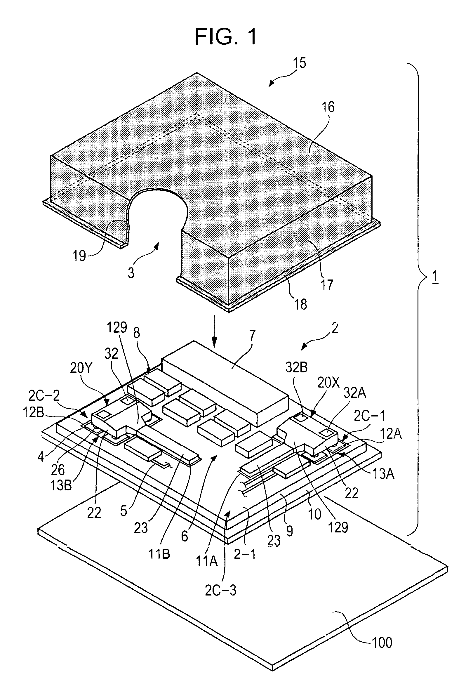
[0087]Referring to FIG. 1, a vibrating gyrosensor 1 has an exterior member including a support substrate 2 and a cover member 15 combined with a first main surface 2-1 of the support substrate 2 to form a component mounting space 3. For example, the vibrating gyrosensor 1 is mounted on a video camera to serve as a mechanism for correcting motion blurring. Also, for example, the vibrating gyrosensor 1 is used for a virtual reality device to serve as a motion detector or used for a car navigation system to serve as a direction detector.

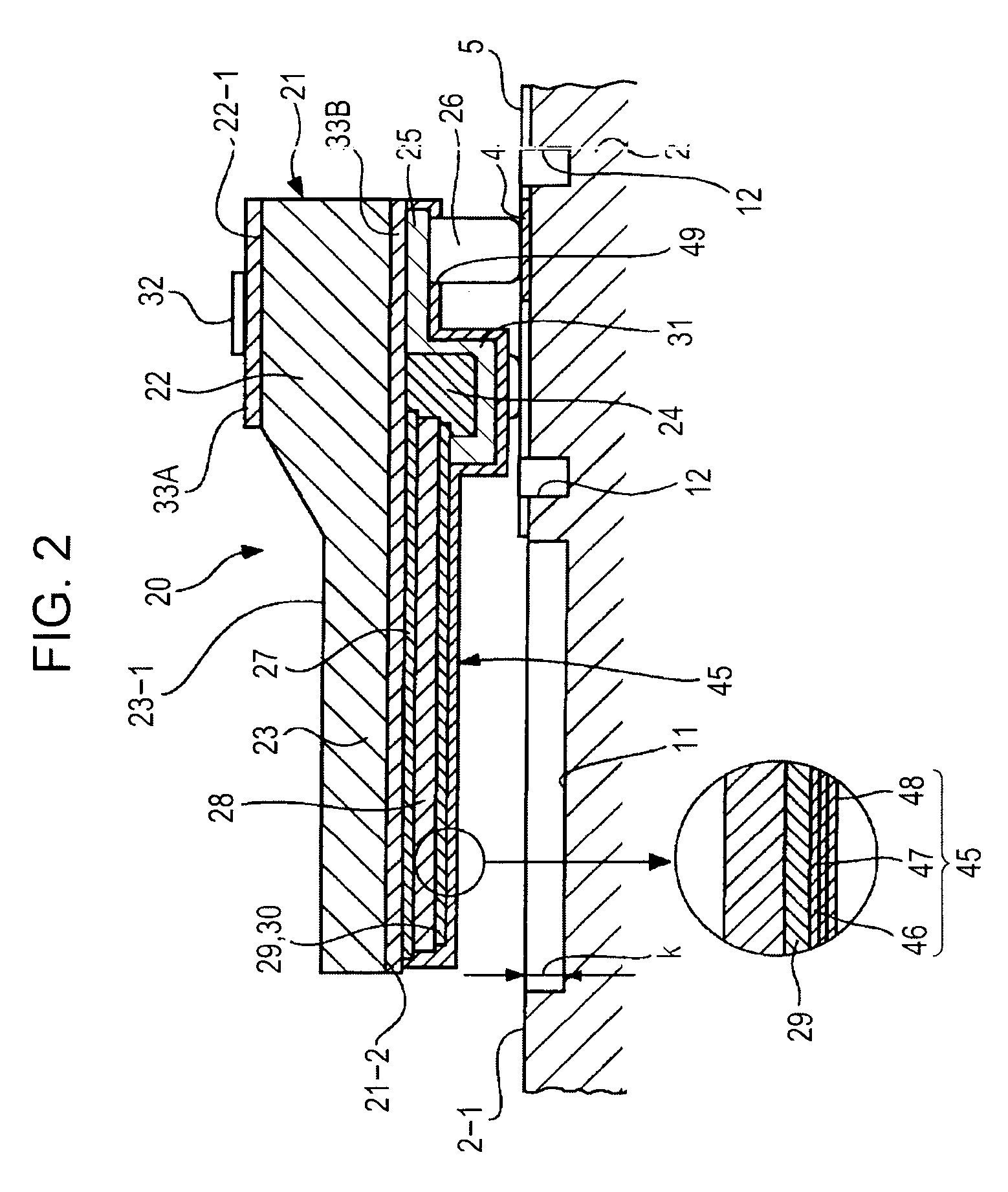
[0088]The vibrating gyrosensor 1 includes, for example, a ceramic substrate or a glass substrate as the support substrate 2. Also, a predetermined wiring pattern 5 having a plurality of lands 4 is formed on the first main surface 2-1 of the support substrate 2 to form a component mounting region 6. In the component mounting region 6 are mixed-loaded a pair of first and second vibrating elements 20X and 20...

second embodiment

[0271]In the above-described first embodiment, the ICP-RIE (inductively coupled plasma reactive ion etching) method is used in the step of forming the outside groove 39 for cutting off the outer shape of each vibrator part 23 from the silicon substrate 21. This method is excellent in that a vertical groove is formed in the silicon substrate 21 at a high aspect ratio.

[0272]However, in use of the large silicon substrate 21 (large wafer diameter), as schematically shown in FIG. 48A, it may be difficult to form all vibrating parts 23 each having ideal vertical walls on both sides in the substrate. Namely, as schematically shown in FIG. 48B, the vibrator parts 23 having asymmetric shapes are formed in the peripheral region of the substrate due to a gas flow distribution, a plasma distribution, or the like in a plasma processing chamber.

[0273]When the vibrator part 23 has a symmetric shape, an ideal vibration mode in a vertical vibration direction occurs (FIG. 48A), and the detection sign...

third embodiment

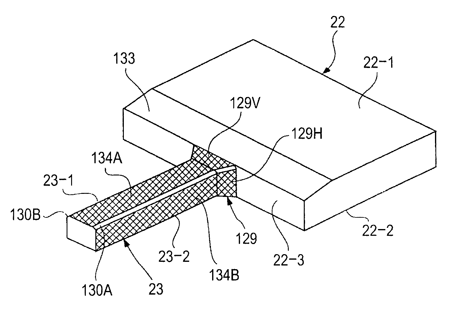
[0286]In the above-described first embodiment, the ICP-RIE method is used in the step of forming the outside groove 39 for cutting off the outer shape of each vibrator part 23 from the silicon substrate 21. This method is excellent in that a vertical groove is formed in the silicon substrate 21 at a high aspect ratio.

[0287]When a linear groove is formed by general etching, an edge at a right angle (between the side in the groove width direction and the side in the groove length direction) is not precisely formed in the groove, and a curved edge is often formed. Therefore, in forming the outside groove 39, as shown in FIG. 51, the root parts 23R1 and 23R2 of the vibrator part, which correspond to the respective boundaries between the both sides of the vibrator part 23 and the side 22-3 of the base part 22, are formed in curved planar shapes. By using this etching property, the horizontal reinforcing part 129H is formed at the base end of the vibrator part 23 according to the first em...


PUM

PropertyMeasurementUnit
volume resistivityaaaaaaaaaa
angleaaaaaaaaaa
depthaaaaaaaaaa

Abstract

A vibrating gyrosensor includes a support substrate on which a wiring pattern having a plurality of lands is formed, and a vibrating element mounted on a surface of the support substrate. The vibrating element includes a base part having a mounting surface on which a plurality of terminals, and a vibrator part integrally projected in a cantilever manner from one of the sides of the base part and having a substrate-facing surface coplanar with the mounting surface of the base part. The vibrator part has a first electrode layer, a piezoelectric layer, and a second electrode layer, which are formed on the substrate-facing surface in that order. Furthermore, a reinforcing part is formed at the base end of the vibrator part so that the sectional area of the vibrator part gradually increases toward the base part.

Description

CROSS REFERENCES TO RELATED APPLICATIONS[0001]The present invention contains subject matter related to Japanese Patent Application JP 2005-080473 filed in the Japanese Patent Office on Mar. 18, 2005, Japanese Patent Application JP 2005-054844 filed in the Japanese Patent Office on Feb. 28, 2005, Japanese Patent Application JP 2005-176869 filed in the Japanese Patent Office on Jun. 16, 2005, Japanese Patent Application JP 2005-080473 filed in the Japanese Patent Office on Mar. 18, 2005, Japanese Patent Application JP 2005-176870 filed in the Japanese Patent Office on Jun. 16, 2005, and Japanese Patent Application JP 2005-374324 filed in the Japanese Patent Office on Dec. 27, 2005, the entire contents of which are incorporated herein by reference.BACKGROUND OF THE INVENTION[0002]1. Field of the Invention[0003]The present invention relates to an angular velocity sensor used, for example, for detecting motion blurring of a video camera, detecting a motion in a virtual reality device, de...

Claims


Application Information

Patent Timeline
Patent Type & Authority Patents(United States)
IPC IPC(8): H01L41/08G01C19/56G01C19/5642G01C19/5656G01C19/5663G01C19/5783H01L41/187H01L41/22H01L41/23H01L41/332H01L41/335H01L41/338
CPCB81B3/0067G01P15/0802G01C19/5663B81B2201/0285B81B2203/0118F21V15/01F21V1/24F21V1/22F21V17/10F21V19/0085
Inventor INAGUMA, TERUOHONDA, JUNICHISUZUKI, KOJITAKAHASHI, KAZUONAKASHIO, EIJI
Owner SONY CORP
Why Eureka
Try Eureka