Non-redundant safety monitoring for an electric drive mechanism (with a sensor)

a technology of safety monitoring and drive mechanism, applied in the direction of safety arrangements, electrical testing, instruments, etc., to achieve the effect of avoiding assembly expenditure, reducing costs, and saving further redundant transducers

Active Publication Date: 2010-05-25
LENZE AUTOMATION
View PDF16 Cites 6 Cited by
  • Summary
  • Abstract
  • Description
  • Claims
  • Application Information

AI Technical Summary

Benefits of technology

[0024]According to the invention costs can be reduced by saving further redundant tran

Problems solved by technology

Thus, this test signal influences the entire control circuit and, figuratively speaking, represents an unbalance, if one proceeds from th

Method used


Image

  • Non-redundant safety monitoring for an electric drive mechanism (with a sensor)
  • Non-redundant safety monitoring for an electric drive mechanism (with a sensor)
  • Non-redundant safety monitoring for an electric drive mechanism (with a sensor)

Examples


Embodiment Construction

[0030]The following description is intended to convey a thorough understanding of the embodiments described by providing a number of specific embodiments and details involving non-redundant safety monitoring of a sensor for an electric drive. It should be appreciated, however, that the present invention is not limited to these specific embodiments and details, which are exemplary only. It is further understood that one possessing ordinary skill in the art, in light of known systems and methods, would appreciate the use of the invention for its intended purposes and benefits in any number of alternative embodiments, depending on specific design and other needs.

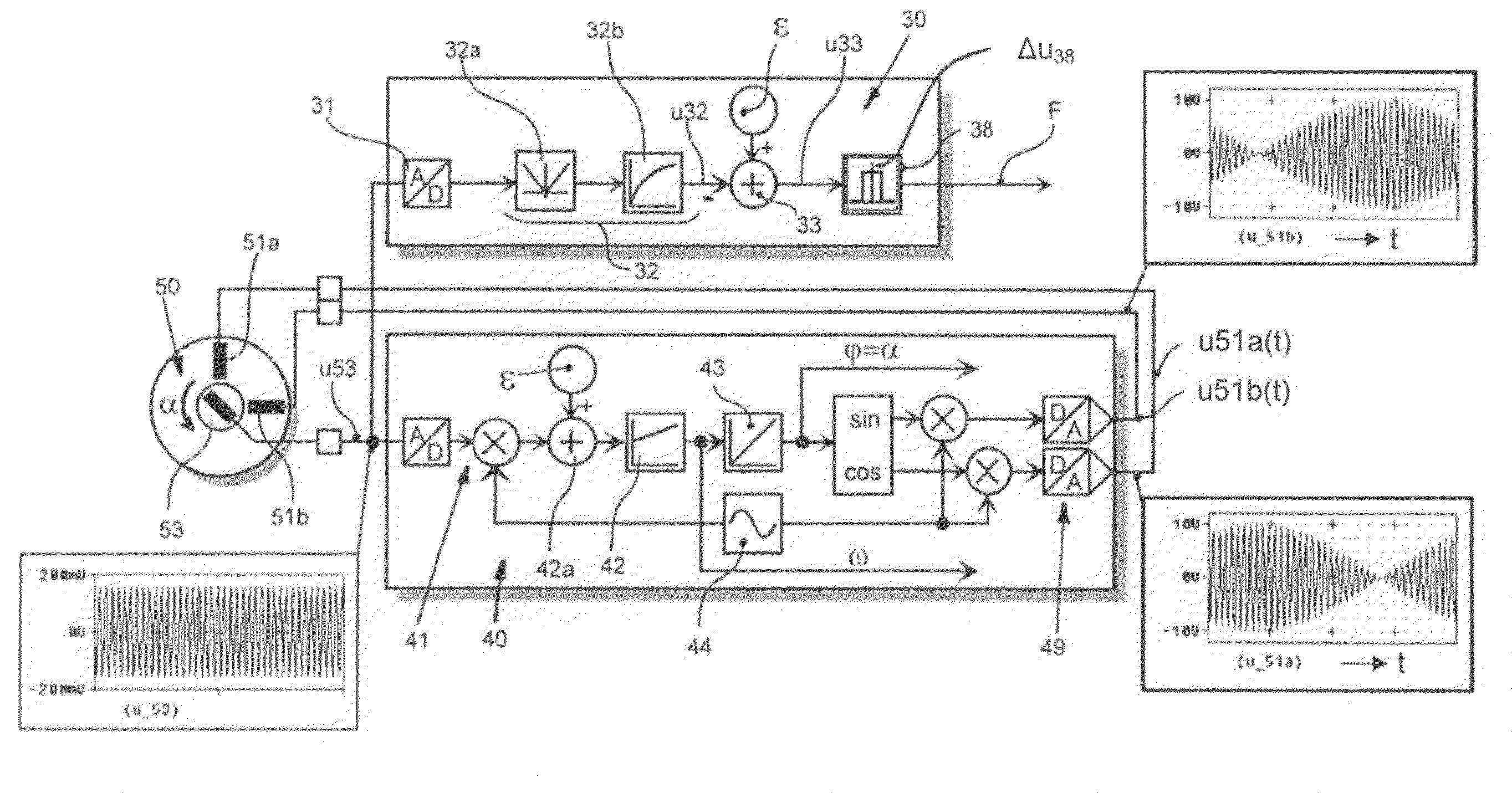
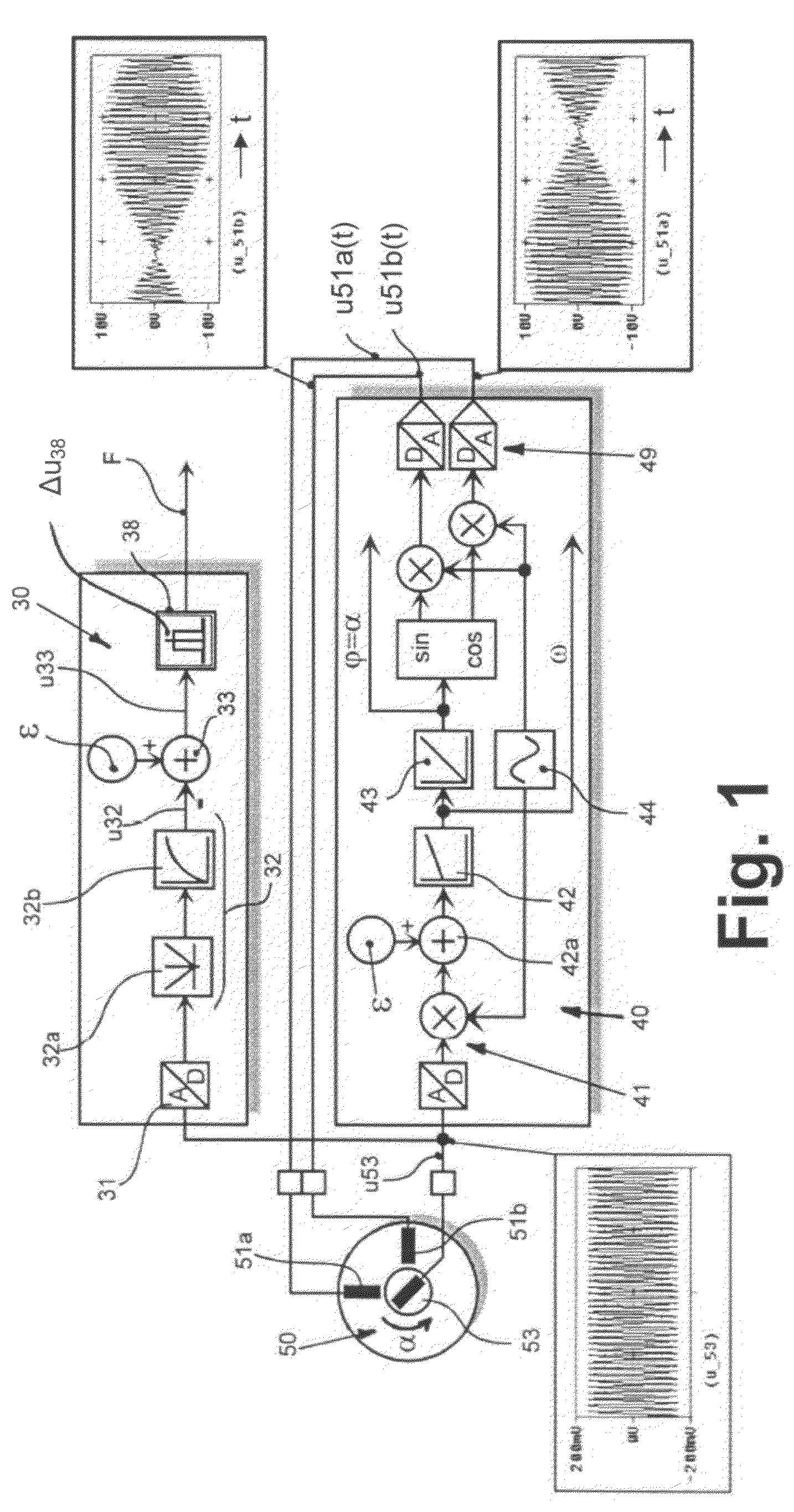
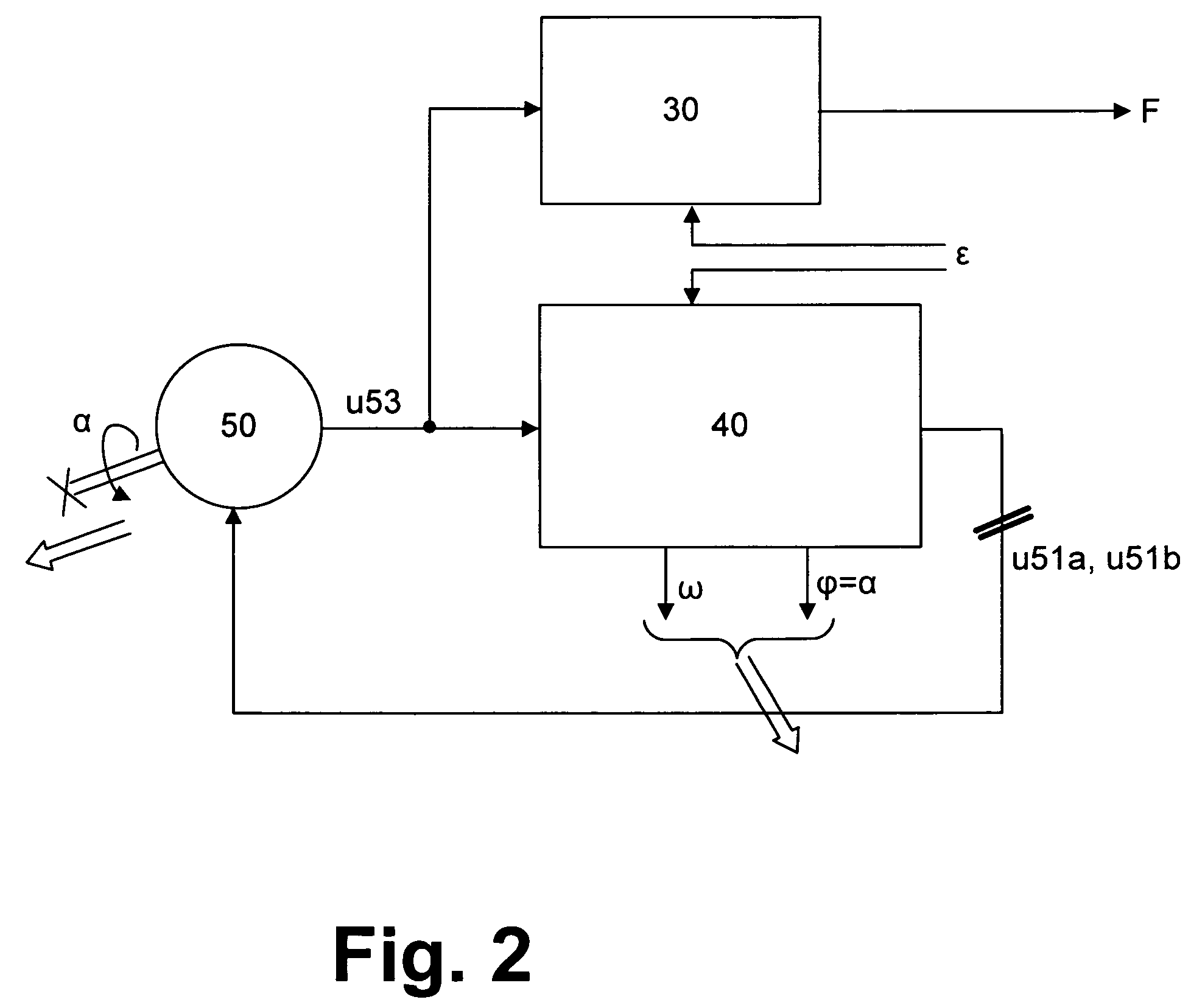
[0031]FIG. 2 illustrates a schematic overview of the functional units of the safety monitoring device described here. A synchro resolver (resolver) 50 is used as a sensor, which is coupled to the shaft of the drive. The synchro resolver comprises transformer-coupled windings, one of which co-rotates with the shaft, whereas the ...


PUM


Abstract

The invention relates to a method for detecting undesired operating conditions of a driving device. A sensor (50) that is transformer-coupled between a stator side and a rotor side is triggered by a control circuit (40) for detecting a position value or a rotational speed value of the drive mechanism. An error signal (F) is emitted, if an undesired operating condition occurs. A test signal (ε) is supplied to a safety monitoring device (30) in order to determine and emit this error signal (F), said test signal being also supplied to the control circuit (40). There, the test signal (ε) acts as an unbalance and is checked as regards its presence in the safety monitoring device.

Description

CROSS REFERENCE TO RELATED APPLICATIONS[0001]This application is a U.S. National Stage Application of International Application No. PCT / DE04 / 00240, filed Feb. 10, 2004, which claims the benefit of DE 103 05 337.9, filed on Feb. 10, 2003, the disclosures of which are incorporated by reference herein in their entireties. PCT / DE04 / 00240 designated the United States and was not published in English.FIELD OF THE DISCLOSURE[0002]The invention relates to a process for monitoring a drive mechanism that is in particular electrically driven and customarily consists of a driving motor, a shaft and an output coupled to the shaft. At least one measuring signal, mostly also several measuring signals, is and / or are required in such drive mechanisms, which are customarily designated as rotational speed, acceleration and position (or angle of rotation) in drive technology.[0003]The invention relates both to a process for detecting an undesired operating condition and to a sensor that is secured agai...

Claims


Application Information

Patent Timeline
IPC IPC(8): G05B23/02G05B9/02
CPCG05B23/0256G05B9/02
Inventor TINEBOR, MANFRED
Owner LENZE AUTOMATION
Why Eureka
Try Eureka