
Composite damper for speaker

a technology for dampers and speakers, applied in the direction of transducer circuits, transducer details, electrical transducers, etc., can solve the problems of increasing the hardness of the damper, not only the production step with extra cost, and the sound quality of the conventional damper is unstable, so as to achieve stable vibration frequency, simple manufacturing process, and good elasticity

Active Publication Date: 2010-05-25
OHARA HIROSHI
View PDF6 Cites 7 Cited by
  • Summary
  • Abstract
  • Description
  • Claims
  • Application Information

AI Technical Summary

Benefits of technology

"The present invention relates to a composite damper for a speaker that has better elasticity and is more durable over time compared to prior dampers. The damper is made of a inner ring surface material, an outer ring surface material, and a plurality of ribs connected between the inner and outer ring surface materials. The inner and outer ring surface materials have a plurality of alternating concentric peaks and valleys. The damper can be integrally molded using a plastic or rubber injection mold process and has stable vibration frequency and excellent sound quality."

Problems solved by technology

However, the design of conventional dampers focuses on element connection not on improvement of elasticity; thereby the conventional dampers have an unstable sound quality.
It needs not only an additional production step with extra cost but also increases hardness of the damper due to the three-layer structure.
Accordingly it has a relatively bad elasticity.
Since the conventional damper is made by single-piece material, once the speaker generates irregular jumps, it will result in a bad sound quality.

Method used


Image

  • Composite damper for speaker
  • Composite damper for speaker
  • Composite damper for speaker

Examples


Embodiment Construction

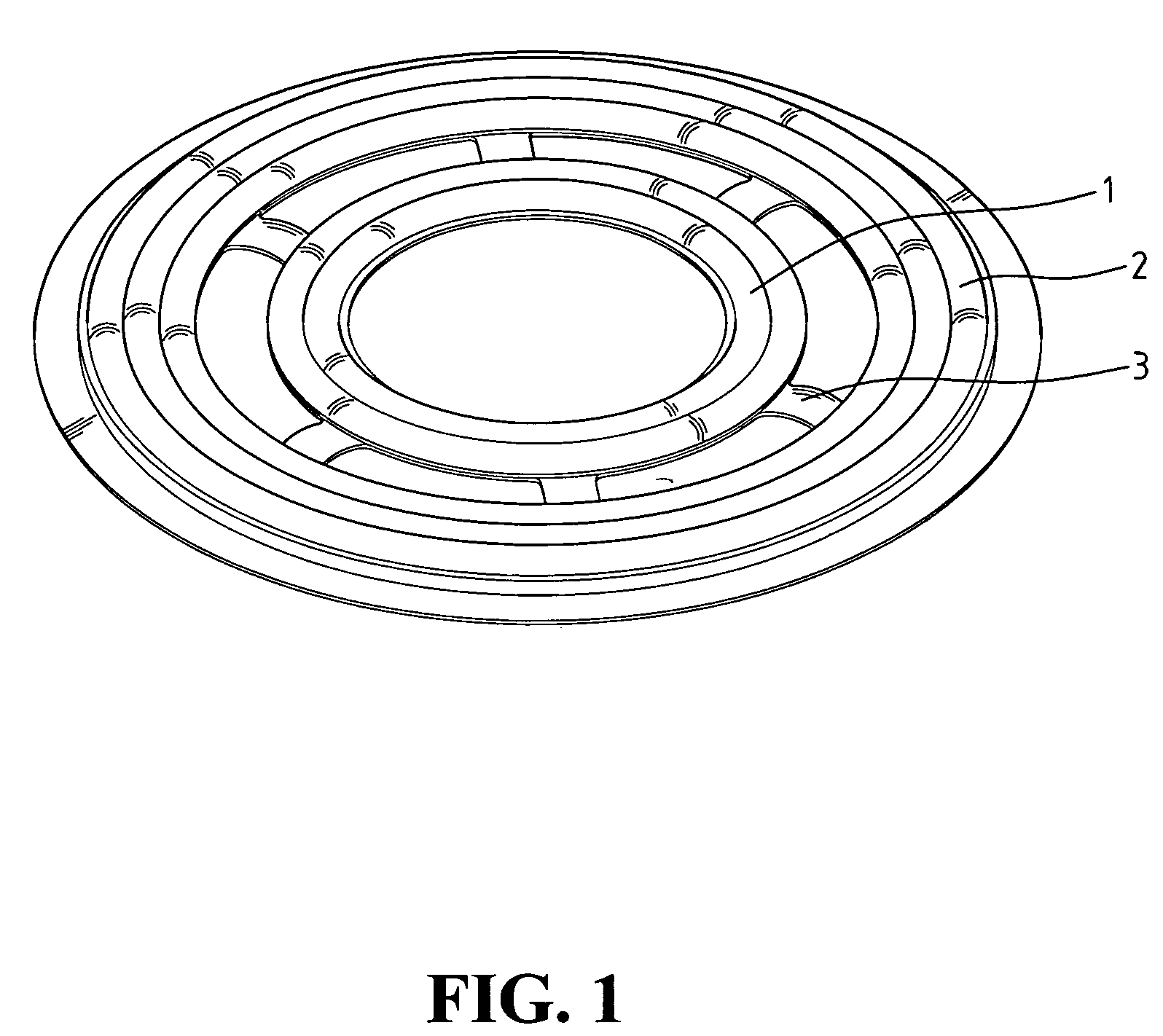
[0021]With reference to FIG. 1, a composite damper for a speaker in accordance with the present invention comprises an inner ring surface material 1, an outer ring surface material 2 and a plurality of ribs 3 connected between the two surface materials 1, 2. The ribs 3 are elastomer. The damper forms a plurality of alternating concentric peaks and valleys on surfaces of the two surface materials 1, 2, so that when it is coupled with a periphery of a voice coil 6 of the speaker (see FIG. 5), it has a more stable vibration frequency due to the structure of the peaks and valleys.

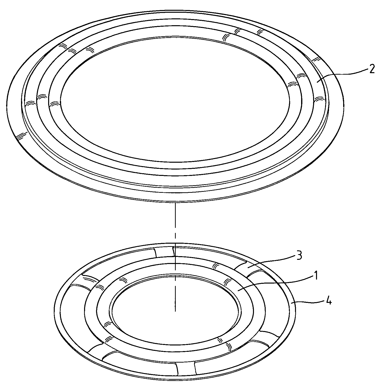
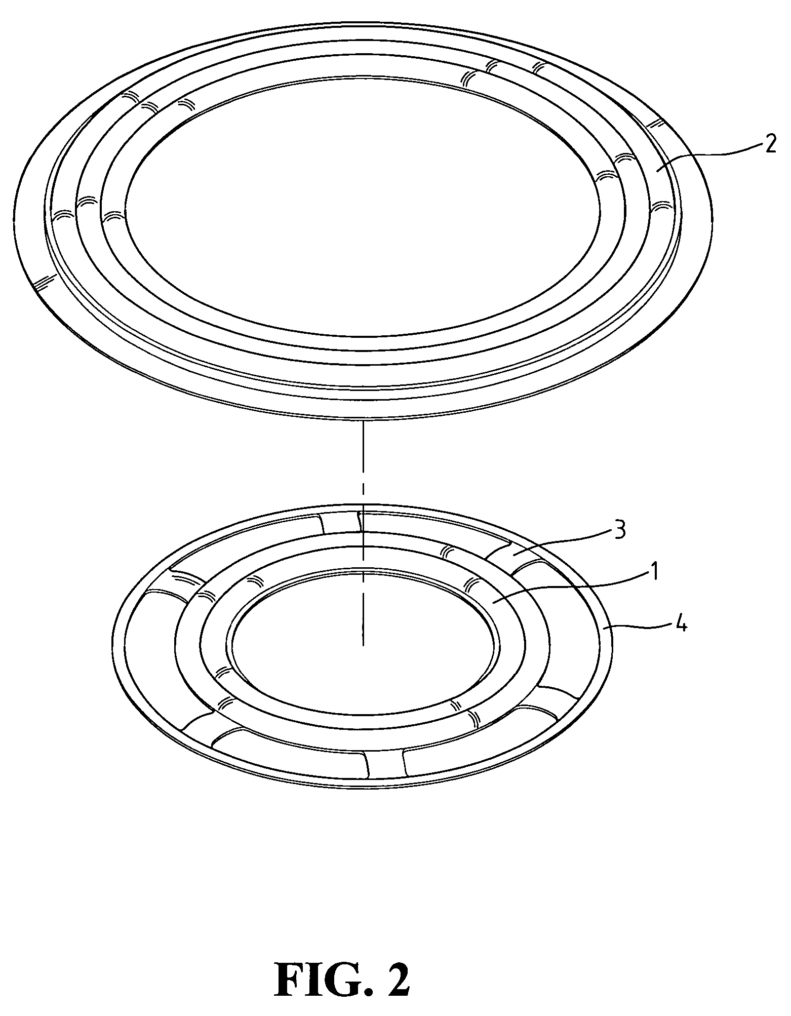
[0022]Referring to FIG. 2, which illustrates a first preferred embodiment of the present invention, the inner ring surface material 1, an outer ring bracket 4 and the ribs 3 connected between the inner ring surface material 1 and the outer ring bracket 4 are integrally molded using a plastic or rubber injection mold process. Then the outer ring bracket 4 is coupled by adhesive with the outer ring surface materi...


PUM


Abstract

A composite damper for a speaker comprises an inner ring surface material, an outer ring surface material, and a plurality of ribs connected between the inner ring surface material and the outer ring surface material. The inner ring surface material and the outer ring surface material have a plurality of alternating concentric peaks and valleys; thereby when it is coupled with a periphery of a voice coil of the speaker, it has a more stable vibration frequency.

Description

BACKGROUND OF THE INVENTION[0001]1. Field of the Invention[0002]The present invention relates to a damper for a speaker, and more particularly to a composite damper having an auxiliary fixing member that is capable of stabilizing sound quality of the speaker.[0003]2. The Prior Arts[0004]A damper for a speaker is mounted on an outer periphery of a voice coil of the speaker. In this way, it can prevent the voice coil from generating irregular jump upon energized with electricity, thereby obtaining a stable sound quality. However, the design of conventional dampers focuses on element connection not on improvement of elasticity; thereby the conventional dampers have an unstable sound quality. When the voice coil is vibrating, it vibrates not only in up and down directions but also in lateral direction. Accordingly, how to make the voice coil stable vibration has become an important issue that needs to be overcome.[0005]An example of improved dampers having an auxiliary fixing member is ...

Claims


Application Information

Patent Timeline
Patent Type & Authority Patents(United States)
IPC IPC(8): H04R25/00
CPCH04R9/045H04R2209/027H04R31/006
Inventor OHARA, HIROSHI
Owner OHARA HIROSHI
Learn More