Speaker device

a speaker device and sound technology, applied in the direction of transducer details, transducers, electrical transducers, etc., can solve the problems of difficult to reduce the weight of the vibration system, difficult to achieve sufficient low-frequency sound reproduction, etc., to improve the output sound pressure level, and increase the magnetic flux

Active Publication Date: 2010-05-25
PANASONIC CORP
View PDF21 Cites 13 Cited by
  • Summary
  • Abstract
  • Description
  • Claims
  • Application Information

AI Technical Summary

Benefits of technology

[0012]In a second aspect based on the first aspect, the vibration system member further includes a diaphragm at least a portion of which is composed of the non-magnet member. The first voice coil bobbin is fixed to the diaphragm. The support system member supports the diaphragm in the gap in a manner which allows the diaphragm to vibrate.
[0039]According to the fifth aspect, it is possible to achieve a speaker device comprising a housing for use in an AV system or the like, and the speaker unit.

Problems solved by technology

However, speaker devices for eventually reproducing sounds require large cabinets so as to sufficiently reproduce sounds in a low frequency region included in music sources.
Therefore, speaker devices carried in the small-size or portable players have small-volume cabinets, so that an acoustic stiffness exhibited by the cabinet is large, and therefore, it is difficult to achieve low-frequency sound reproduction to a sufficient extent.
Therefore, in the conventional speaker device, it is difficult to reduce the weight of the vibration system while keeping the force which gives the negative stiffness.

Method used


Image

  • Speaker device
  • Speaker device
  • Speaker device

Examples


first embodiment

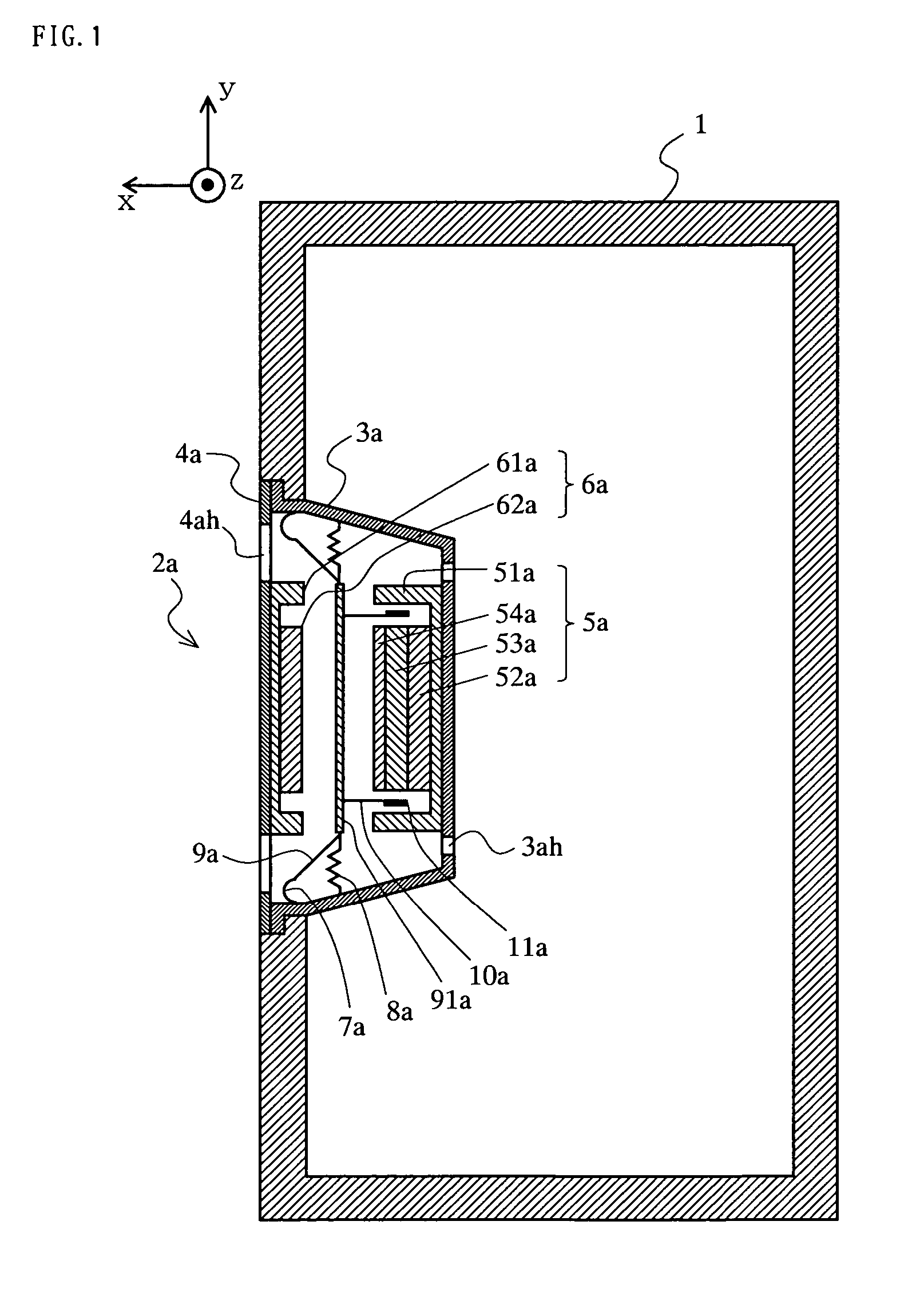
[0086]A speaker device according to a first embodiment of the present invention will be described with reference to FIG. 1. FIG. 1 is a cross-sectional view of a structure of the speaker device of the first embodiment. In FIG. 1, the speaker device of the first embodiment roughly comprises a cabinet 1 and a speaker unit 2a. The speaker unit 2a, which is in the shape of, for example, a circle, is attached to an opening portion formed in a front surface (the positive direction of an x axis) of the cabinet 1. The cabinet 1 is a housing which gives an acoustic stiffness to the speaker unit 2a. The speaker unit 2a is composed of a back surface frame 3a, a front surface frame 4a, a first magnetic circuit 5a, a second magnetic circuit 6a, an edge 7a, a damper 8a, a diaphragm 9a, a voice coil bobbin 10a, and a voice coil 11a.

[0087]The back surface frame 3a has a shape in which an inner portion thereof is projected in the shape of a convex with respect to an outer circumferential portion th...

second embodiment

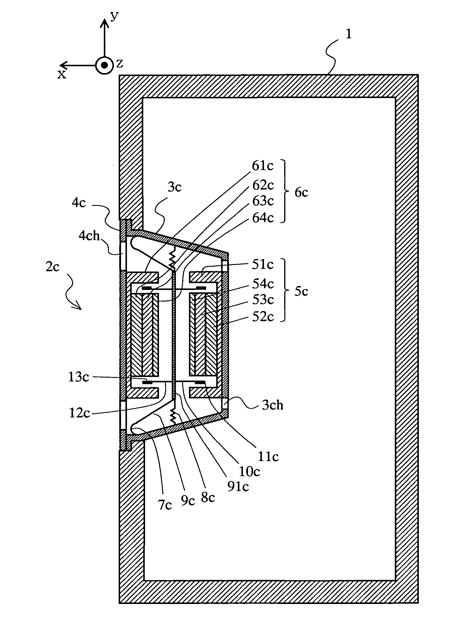
[0102]A speaker device according to a second embodiment of the present invention will be described with reference to FIG. 3. FIG. 3 is a cross-sectional view of a structure of the speaker device of the second embodiment. In FIG. 3, the speaker device of the second embodiment roughly comprises a cabinet 1 and a speaker unit 2c. The speaker unit 2c, which is in the shape of, for example, a circle, is attached to an opening portion formed in a front surface (the positive direction of an x axis) of the cabinet 1. The cabinet 1 is a housing which gives an acoustic stiffness to the speaker unit 2c. The speaker unit 2c is different from the speaker unit 2a of the first embodiment in that both the first and second magnetic circuits both form magnetic gaps, and two voice coil bobbins and two voice coils are provided. Hereinafter, a structure of the speaker unit 2c will be described.

[0103]The speaker unit 2c is composed of a back surface frame 3c, a front surface frame 4c, a first magnetic ci...

third embodiment

[0120]A speaker device according to a third embodiment of the present invention will be described with reference to FIG. 5. FIG. 5 is a cross-sectional view of a structure of the speaker device of the third embodiment. In FIG. 5, the speaker device of the third embodiment roughly comprises a cabinet 1 and a speaker unit 2e. The speaker unit 2e, which is in the shape of, for example, a circle, is attached to an opening portion formed in a front surface (the positive direction of an x axis) of the cabinet 1. The cabinet 1 is a housing which gives an acoustic stiffness to the speaker unit 2e. The speaker unit 2e is different from the speaker unit 2c of the second embodiment in that a second magnetic circuit is supported by a column disposed in a gap between the second magnetic circuit and a first magnetic circuit, so that the front surface frame is no longer required, and an outer appearance thereof is similar to that of conventional speaker units, and that a magnetic material does not...


PUM


Abstract

A speaker device that comprises a cabinet and a speaker unit. The speaker unit is attached to an opening portion formed in a front surface of the cabinet. The speaker unit has a back surface frame, a front surface frame, a first magnetic circuit, a second magnetic circuit, an edge, a damper, a diaphragm, a voice coil bobbin, and a voice coil. A non-magnet member which is a portion of the diaphragm, the first magnetic circuit, and the second magnetic circuit play a role as a negative stiffness mechanism to suppress an influence of an acoustic stiffness, thereby achieving a small-size speaker device capable of reproducing low-frequency sound.

Description

TECHNICAL FIELD OF THE INVENTION[0001]The present invention relates to a speaker device and, more particularly, to a speaker device which achieves low-frequency sound reproduction using a small-size cabinet.BACKGROUND ART OF THE INVENTION[0002]Conventionally, audio devices are becoming more digitalized, and players for reproducing music sources are becoming smaller and more portable. However, speaker devices for eventually reproducing sounds require large cabinets so as to sufficiently reproduce sounds in a low frequency region included in music sources. Therefore, speaker devices carried in the small-size or portable players have small-volume cabinets, so that an acoustic stiffness exhibited by the cabinet is large, and therefore, it is difficult to achieve low-frequency sound reproduction to a sufficient extent.[0003]Therefore, a speaker device has been disclosed in which a limit of low-frequency sound reproduction which is determined by the volume of a cabinet is improved (see, f...

Claims


Application Information

Patent Timeline
Patent Type & Authority Patents(United States)
IPC IPC(8): H04R1/00H04R1/28H04R9/02H04R9/04
CPCH04R1/22H04R9/025H04R9/04H04R2499/15H04R2400/11H04R2499/13H04R2307/027
Inventor MATSUMURA, TOSHIYUKISAIKI, SHUJI
Owner PANASONIC CORP
Why Eureka
Try Eureka