Device for releasing a spear shaft of a spear gun for scuba diving or the like

a spear gun and shaft technology, applied in the field of underwater activities, can solve the problems of not allowing the adjustment of the trigger stroke nor the force necessary to pull, and the spear may be accidentally released

Inactive Publication Date: 2010-06-01
CRESSI SUB
View PDF7 Cites 9 Cited by
  • Summary
  • Abstract
  • Description
  • Claims
  • Application Information

AI Technical Summary

Benefits of technology

[0006]Accordingly, it is an object of the present invention to provide a device for releasing a spear shaft of a spear gun for scuba diving or the like that allows the operating stroke of the trigger and / or the effort necessary to pull the trigger to be graduated in accordance with a selected diver's characteristics and needs.
[0007]Another object of the present invention is to provide a device for releasing a spear shaft of a spear gun that provides for quick and easy adjustment of the trigger's stroke and / or of the force necessary to pull the trigger through use of a kinematic chain that is neither complicated to manufacture nor to assemble.

Problems solved by technology

The kinematic chains often used to operate spear guns, though useful, do not permit adjustment of the stroke of the trigger nor of the force necessary to pull it.
If the stroke of the trigger is short, and the spear gun is operated by an inexperienced scuba diver who lacks a feel for the trigger, or in the event of other circumstances such as a diver's use of very thick gloves, the spear may be accidentally released.
Simply put, adjustments of the trigger's stroke and / or graduating the effort required for a diver to pull the trigger has been found difficult and has yet to provide a solution that is both safe and simple.

Method used


Image

  • Device for releasing a spear shaft of a spear gun for scuba diving or the like
  • Device for releasing a spear shaft of a spear gun for scuba diving or the like
  • Device for releasing a spear shaft of a spear gun for scuba diving or the like

Examples


Embodiment Construction

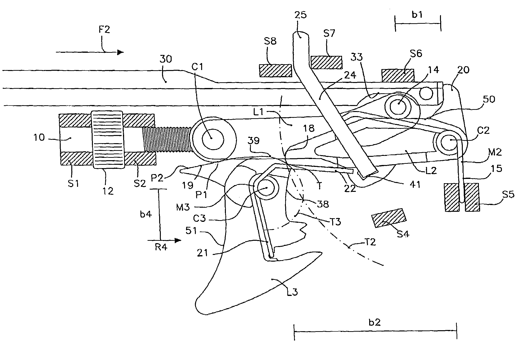
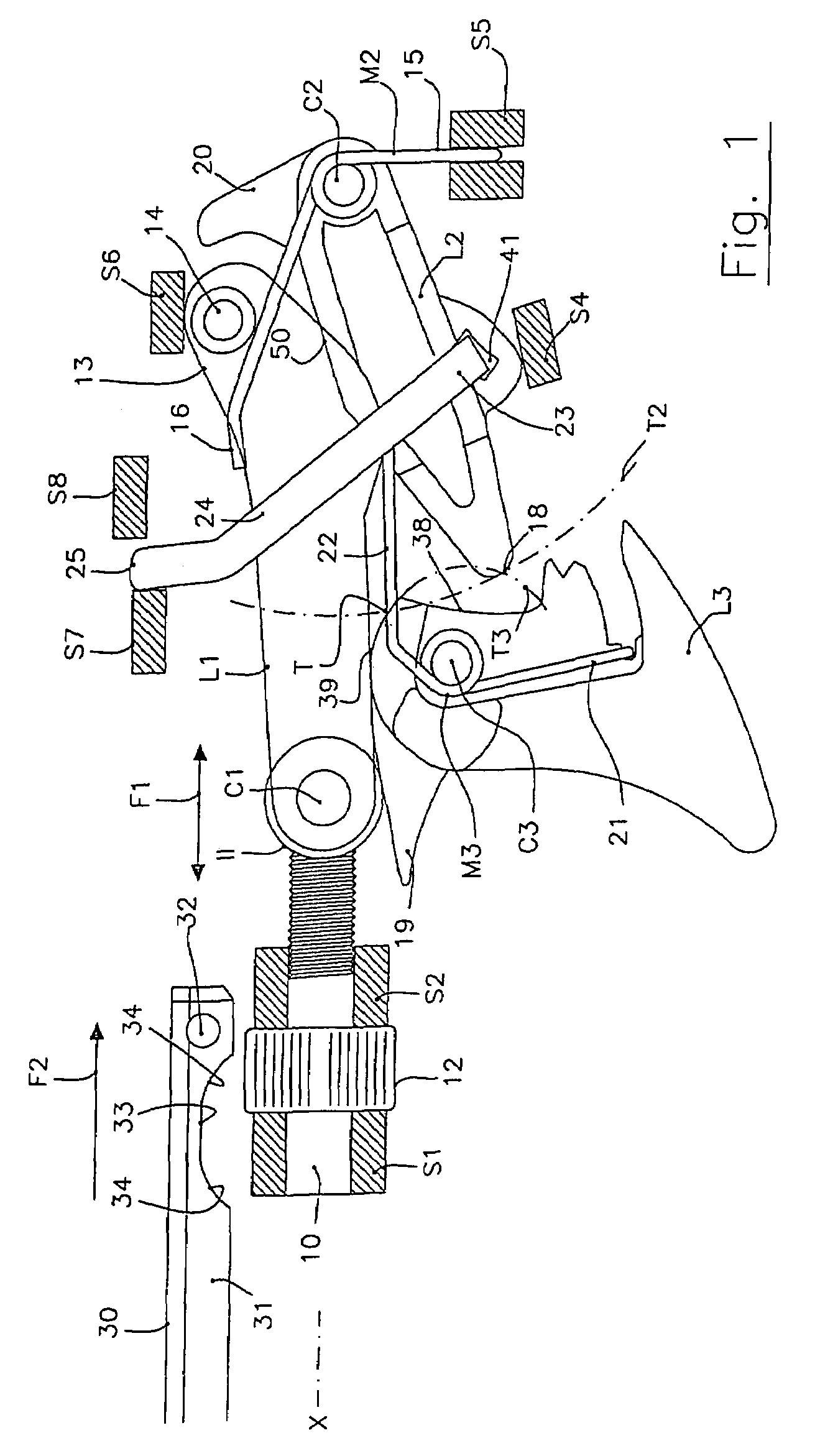
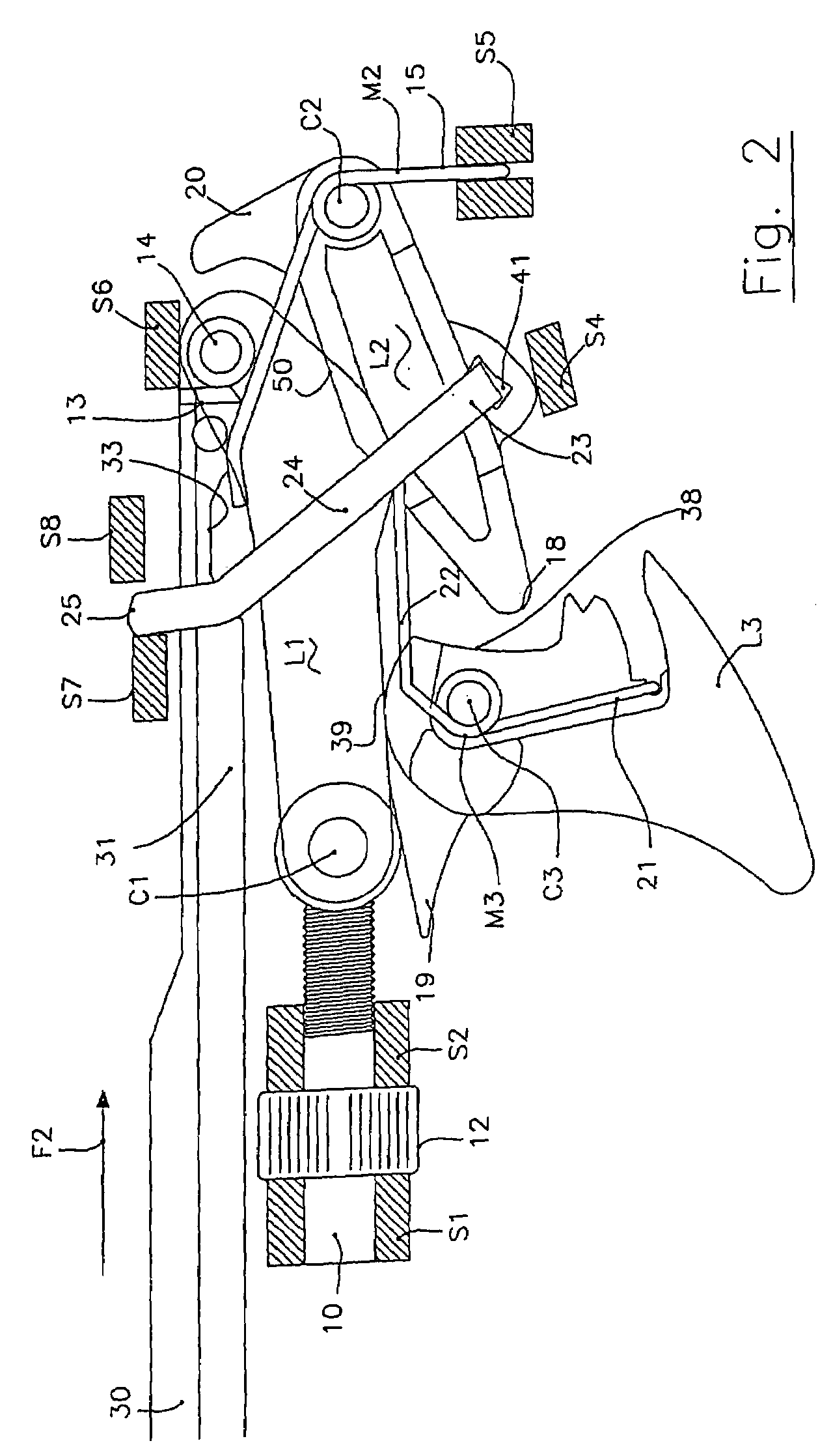
[0017]As set forth herein, illustration of spear guns for scuba divers is restricted generally to the elements that comprise a device for releasing a spear shaft of the spear gun, according to various apsects of the present invention. Consequently, swivel pins for articulation of the various component parts, and abutment elements for the moving parts, are shown schematically only. The pins and abutment elements are attached integrally to the frame of the gun, which is not shown in its entirety, the remaining structural and functional aspects of spear guns being known by those skilled in the art. As their further description is considered unnecessary for illustration of the present invention, the foregoing discussion is not intended to limit the environment.

[0018]Referring now to the drawings and, more particularly, to FIGS. 1-6, there is shown generally a specific, illustrative device for releasing a spear shaft of a spear gun for scuba diving or the like, according to various aspec...


PUM


Abstract

A device is provided for releasing a spear shaft of a spear gun for scuba diving or the like. The shaft has a latch element formed on a first lever pivotally connected at its front end to a screw attached to and integrally with a frame of the gun, the lever being maintained elastically in a resting position. The gun has a trigger with an abutment portion forced elastically against the front end of the first lever extending forward of a convex upper surface. The convex upper surface intersects a concave surface at an edge that traces a first circular trajectory when the trigger is rotated. A second lever is rotatably connected to the frame, the front end of the second lever being movable along a second circular trajectory intersecting the first circular trajectory. An arm of the second lever extends so as to intersect the trajectory of the spear shaft when it is loaded in the gun, such that the shaft abuts the latch element first, thereby moving the first lever away from its resting position, until it engages a shaped cavity of the shaft, and subsequently abuts the arm of the second lever. This causes the second lever to turn until it abuts the first lever in line with the latch element, simultaneously raising its front end up to and against the convex surface of the trigger. The front end of the first lever is slidingly connected to a screw, such that the first lever may be variably displaced, thereby adjusting the force applied by the second lever to the trigger.

Description

FIELD OF THE INVENTION[0001]The present invention relates generally to underwater activities and, more particularly, to spear guns for use in fishing, underwater hunting and the like..BACKGROUND OF THE INVENTION[0002]Conventional spear guns, such as those utilized in scuba diving, typically comprise a frame having a longitudinally elongated body mounting, at a rear end, a grip and a trigger. A shaft of a spear is mounted to a front end of the frame, the shaft being mounted slidingly on the elongated body of the frame. The spear is then launched toward a desired target, e.g., a fish, by pulling the trigger. The rear end of the shaft is usually connected to a string line for retrieval of the spear and any prey that may have been snagged by the diver.[0003]The force for propelling the spear is provided by a pair of cables, made of an elastic material, that are stretched and hooked to the shaft of the spear when the diver loads the gun. Once the trigger is pulled, the spear is released,...

Claims


Application Information

Patent Timeline
Patent Type & Authority Patents(United States)
IPC IPC(8): F41B7/04
CPCF41B7/046A01K81/00
Inventor PEDEMONTE, STEFANO
Owner CRESSI SUB
Why Eureka
Try Eureka