Multiple punch and die assembly providing hand disassembly, punch length adjustment and replacement

a technology of multiple punches and dies, applied in the field of punches and die art, can solve the problems of damage to the machine, damage to the punch or other parts of the equipment, and the standard tooling used for single station punches is not suitable, so as to prevent damage to inactive punches or associated equipmen

Active Publication Date: 2010-06-01
MATE PRECISION TOOLING
View PDF15 Cites 25 Cited by
  • Summary
  • Abstract
  • Description
  • Claims
  • Application Information

AI Technical Summary

Benefits of technology

[0021]The present invention provides an improved multi-punch and die assembly that is adapted to be placed for operation in a high speed, computer-controlled punch press having a punch ram for imparting movement to a selected punch that is held in a punch assembly for carrying out a punching or forming operation. The multi-punch assembly has a plurality of circumferentially arranged, selectively operable punches that are slideably mounted for independent movement within the multi-punch assembly so as to contact a workpiece when moved to an operating position by the punch ram. During operation, the punches are rapidly repositioned between strokes so as to be selectively struck by the ram whereby as one punch is driven to an operating position, at least one other punch remains inactive. In one aspect of the invention, a workpiece protector comprising a punch lifter is operatively associated with each punch for supporting each of the inactive punches in a raised position as an active punch is moved by the ram to the active, i.e. operating position to thereby eliminate scoring or marking of the sheet material or other workpiece that is being punched. A further aspect of the invention is the provision of a manually moveable retainer on the punch assembly that can be moved by hand between a punch-releasing and punch-retaining position for holding the punches within the multi-punch assembly during operation while allowing removal and adjustment of punches without hand tools. Another aspect of the invention is the prevention of stress fractures that formerly occurred in die carriers by distributing support for the dies between two different die components which contact the dies thereby reducing impact stress on the carrier as the ram drives the punch through the workpiece.

Problems solved by technology

Some are not suited for standard tooling used for single station punches since they required stations of special construction or special tooling that cannot be used in standard equipment such as the well-known “thick turret” style tooling.
In addition, vibration or impact shock will occasionally jar one or more of the unused punches causing it to be elevated enough above its normal resting position to strike the punch ram as punch assemblies are rapidly indexed from one position to another during operation.
When this happens, it can, of course, severely damage the punch or other parts of the equipment.
The Matrix company of Schio Italy makes a thick turret punch such as a ½″ station punch with no center shaft, but occasionally one of the inactive punches can be jarred enough to bounce upwardly a fraction of an inch as the punches are rapidly switched between stations under the control of the punch press computer and when elevated in this way, the punch can accidentally strike the ram causing damage to the machine.
Thus, there is no positive way of preventing damage from parts accidentally striking one another during operation.
A still further disadvantage of prior multi-punches is the tendency for one or more of the unused punches to mark or otherwise score the top of the workpiece as the active punch is driven through the workpiece.
Die carriers are also subject to stress cracking.

Method used


Image

  • Multiple punch and die assembly providing hand disassembly, punch length adjustment and replacement
  • Multiple punch and die assembly providing hand disassembly, punch length adjustment and replacement
  • Multiple punch and die assembly providing hand disassembly, punch length adjustment and replacement

Examples


Embodiment Construction

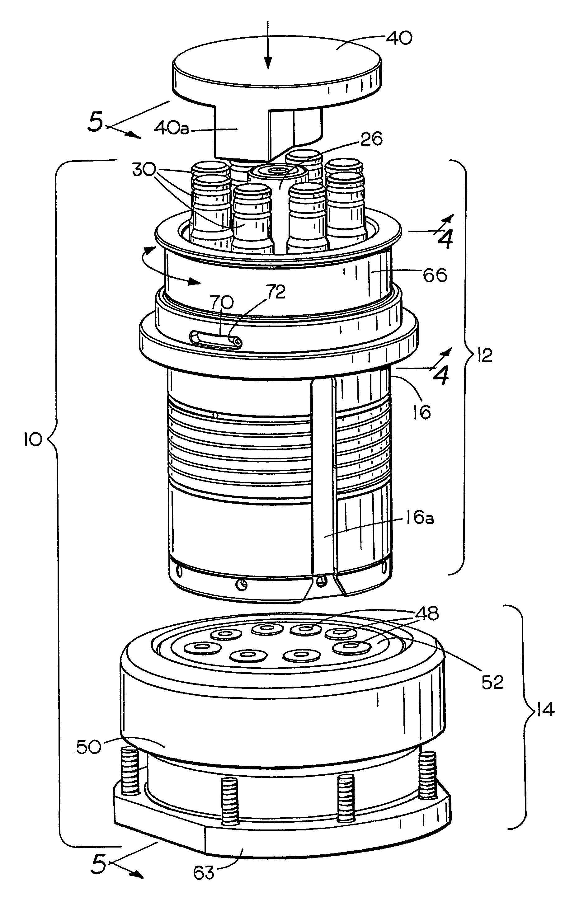
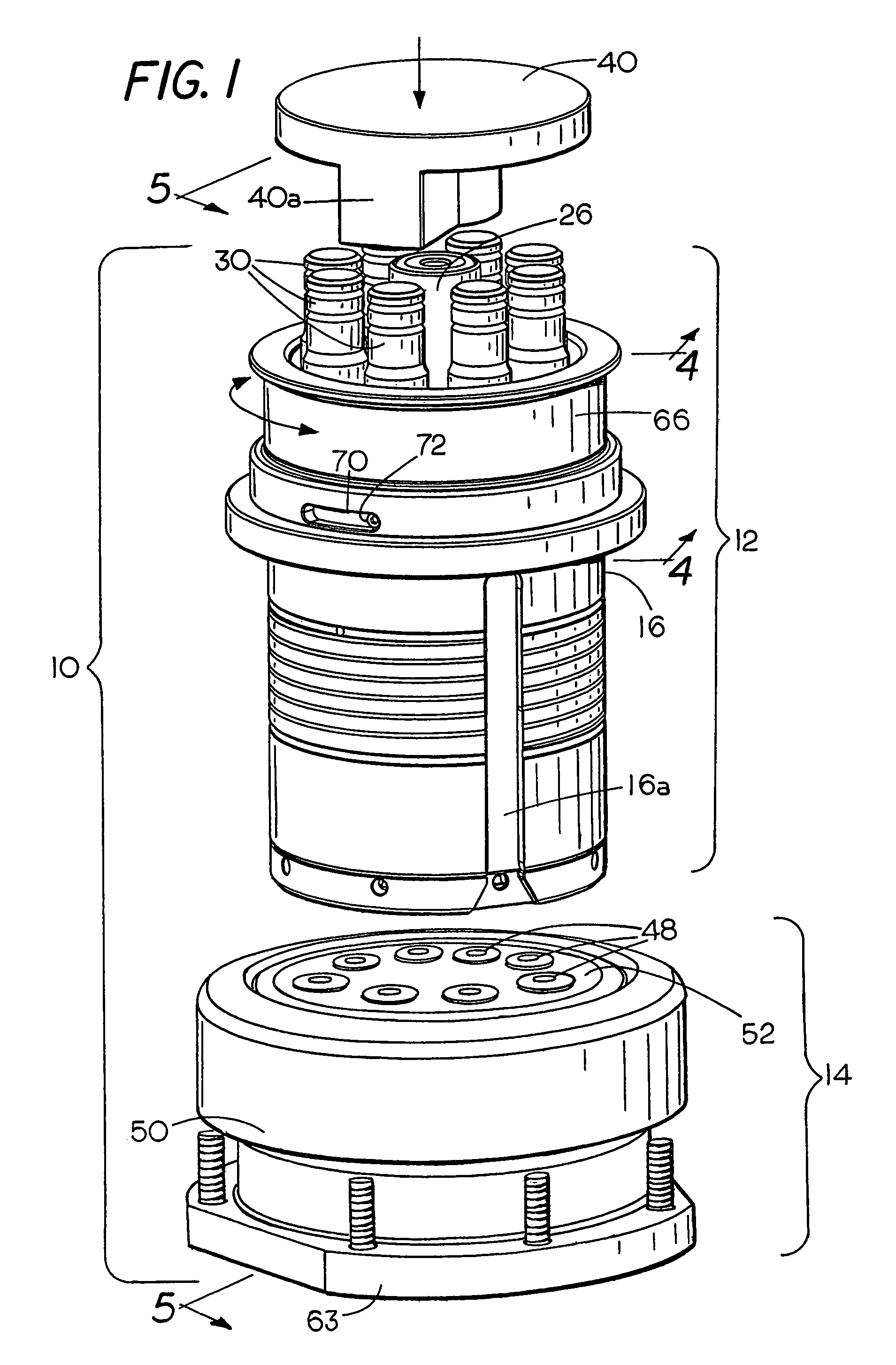
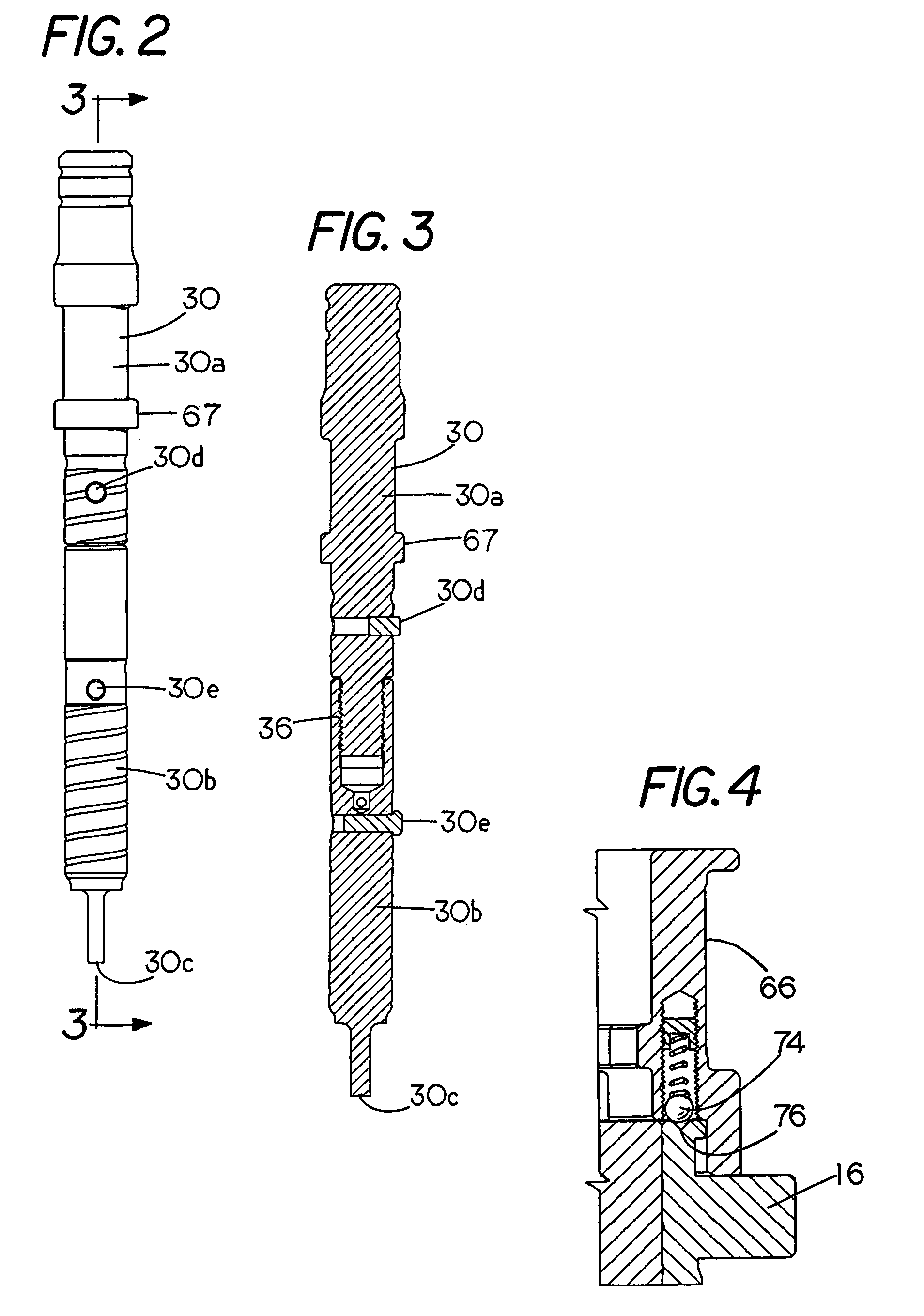
[0022]As shown in FIG. 1, the punch and die assembly is indicated generally by the numeral 10 and includes a multiple punch assembly or multi-punch 12 and a multiple die assembly 14 that is aligned beneath the punch assembly 12 during operation. The punch assembly 12 includes an upper tool holder 16 supported within a housing 17 that is mounted on an upper punch press turret 20 during operation in a conventional manner with its lower end extending through an opening in the upper press turret 20 as shown. The punch press and its turrets per se form no part of the present invention. As seen in FIG. 1, the punch holder 16 is provided with a vertical slot 16a that is keyed to the housing 17 by means of a pin 19 (FIG. 5) to hold all of the punches 30 in a desired angular orientation about the central axis of the assembly. During operation, the housing 17 and multi-punch assembly 12 is rapidly rotated in a conventional manner about the vertical central axis between each operation of the r...


PUM

PropertyMeasurementUnit
lengthaaaaaaaaaa
impact stressaaaaaaaaaa
stress crackingaaaaaaaaaa

Abstract

A multiple punch and multiple die assembly has a workpiece protector which is a punch lifter that is operatively associated with each punch for supporting each of the punches in an inactive position as an active punch is moved by the ram to the active, i.e. operating position to thereby eliminate scoring or marking of the sheet material or other workpiece that is being punched. To eliminate the need for hand tools and hand assembly or disassembly, a manually moveable retainer on the punch assembly is provided that can be moved by hand between a punch-releasing and punch-retaining position for holding the punches within the multi-punch assembly during operation. To prevent stress fractures that formerly occurred in die carriers, support of each die is distributed between two different die components thereby reducing impact stress on the carrier as the ram drives the punch through the workpiece.

Description

FIELD OF THE INVENTION[0001]The present invention relates to the punch and die art and more particularly to a multiple punch and die assembly adapted for use in a punch press for punching or forming sheet material.BACKGROUND OF THE INVENTION[0002]In the punch and die art and particularly in the field of high-speed automated forming and punching equipment for punching and forming workpiece, e.g., sheet metal and especially in the case of automated turret punch presses, the punch presses are operated by computer to rapidly perform a series of punching or forming operations sequentially. These punch presses which by themselves form no part of the present invention are typically provided with aligned upper and lower turrets that rotate and are indexed intermittently between punching operations. The turrets may hold as many as a dozen or more separate punches that are used in sequence for performing given operations. A multiple punch or “multi-punch” has several punches in a single casin...

Claims


Application Information

Patent Timeline
Patent Type & Authority Patents(United States)
IPC IPC(8): B26D5/08B26F1/14G06K1/00
CPCB21D22/08B21D28/346B21D28/125B21D28/12Y10T83/8727Y10T83/8867Y10T83/9423Y10T83/8732Y10T83/8759Y10T83/04Y10T83/8748Y10T83/944
Inventor THIELGES, BRUCE M.SCHNEIDER, JOSEPH C.
Owner MATE PRECISION TOOLING
Why Eureka
Try Eureka