
Liquid crystal display apparatus

a technology of liquid crystal display and display screen, which is applied in the direction of electrical apparatus casings/cabinets/drawers, television systems, instruments, etc., can solve the problem that the technique cannot be directly applied to the liquid crystal display screen of the television receiver, and achieve the effect of improving material yield, reducing costs, and improving material yield

Inactive Publication Date: 2010-06-01
FUNAI ELECTRIC CO LTD
View PDF5 Cites 16 Cited by
  • Summary
  • Abstract
  • Description
  • Claims
  • Application Information

AI Technical Summary

Benefits of technology

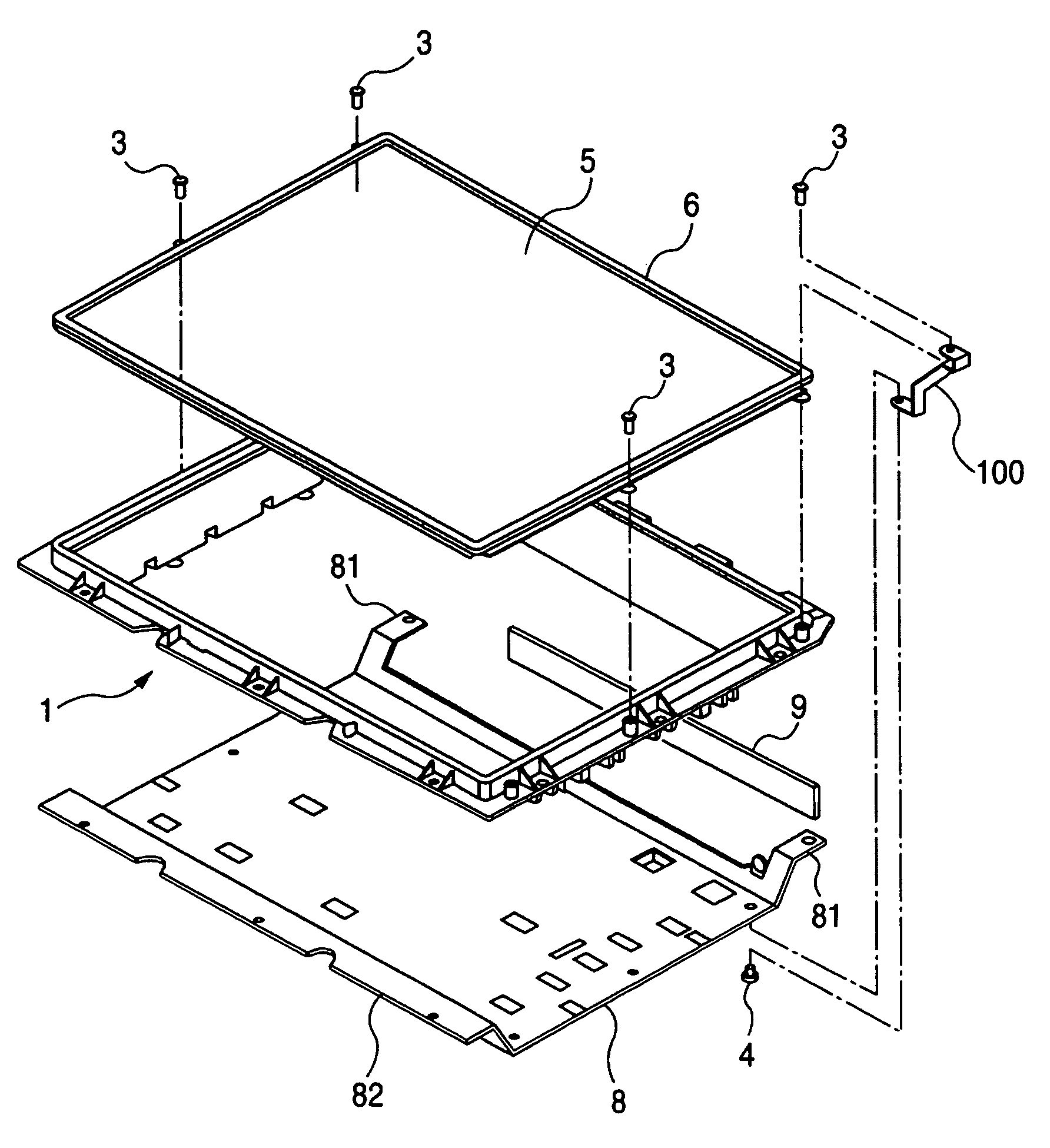
[0012]However, according to FIG. 6, even though the earth fitting 100 has been concurrently clamped onto the edge frame member 6 with the screw 3 for fixing the edge frame member 6 to the frame 1, the earth fitting 100 in a complex shape and the screw 4 that joins the earth fitting 100 to the backboard member 8 are necessary. Therefore, even when the mounting pieces have been eliminated from the left and right side portions of the backboard member 8 to improve a material yield thereof and costs have been thereby reduced as described above, since the earth fitting and screws for mounting the same are required as extra, the effect of cost reduction owing to the material yield of the backboard member 8 may be reduced by the components required as extra such as an earth fitting.
[0013]The present invention has been made in view of the above circumstances, and it is an object thereof to provide a liquid display unit that can prevent exerting an adverse effect on a liquid crystal panel by making it possible, when static electricity of a human body has jumped thereinto, to lead the static electricity from an edge frame member to a backboard member regardless of being able to eliminate the necessity of use an earth fitting and screws for mounting the earth fitting as extra.
[0014]In addition, it is an object of the present invention to provide a liquid crystal display apparatus that can prevent exerting an adverse effect on a liquid crystal panel by making it possible to lead static electricity from an edge frame member to a backboard member without using the components such as an earth fitting described above as extra even when the mounting pieces are eliminated from the left and right side portions of the backboard member as described above.

Problems solved by technology

The above-related arts merely propose countermeasures against static electricity for small-sized liquid crystal display apparatuses used for cameras and navigation systems, therefore, such techniques cannot be directly applied to liquid crystal display apparatuses for television receivers that are often constructed in larger sizes than the same.

Method used


Image

  • Liquid crystal display apparatus
  • Liquid crystal display apparatus
  • Liquid crystal display apparatus

Examples


Embodiment Construction

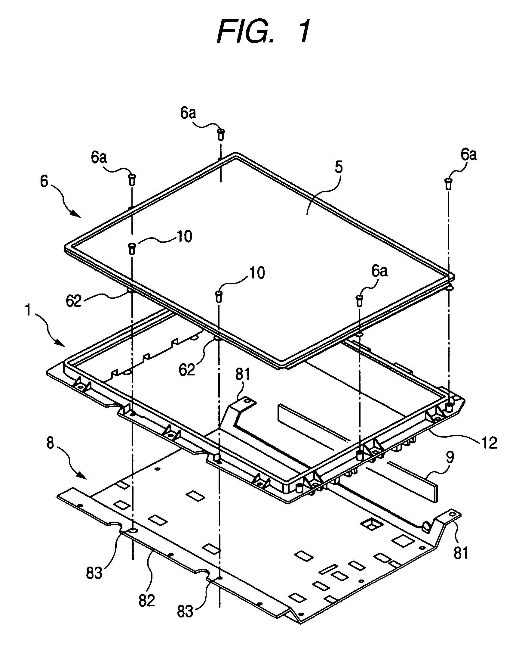
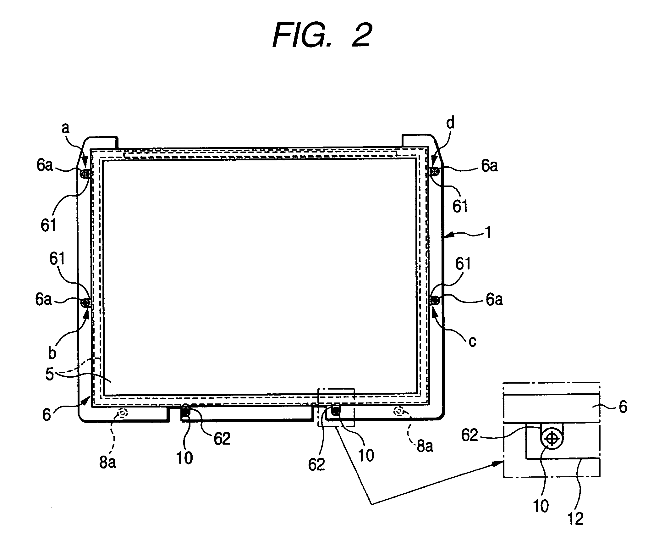
[0032]FIG. 1 is a schematic exploded perspective view of a main part of a liquid crystal display apparatus according to an embodiment, FIG. 2 is a front view of the same liquid crystal display apparatus, FIG. 3 is a rear view of the same liquid crystal display apparatus, FIG. 4 is an enlarged cross-sectional view of a part along a line V-V of FIG. 3, and FIG. 5 is a horizontal cross-sectional view of a backboard member from an arrow VIII direction of FIG. 3.

[0033]The liquid crystal display apparatus according to the present embodiment is formed for a television receiver using a rectangular liquid crystal panel 5 made of an approximately 15-inch relatively small-sized liquid crystal module, includes, as in FIG. 1, as main components thereof, a resin-made frame 1 shaped in a roughly loop form, a metallic edge frame member 6, and a metallic backboard 8, and does not necessitate the earth fitting 100 and screws 3 and 4 for mounting the same shown in FIG. 6 and FIG. 7.

[0034]The frame 1 h...


PUM

PropertyMeasurementUnit
sizeaaaaaaaaaa
sizeaaaaaaaaaa
electrically conductiveaaaaaaaaaa

Abstract

On both sides of a resin-made frame, a metallic edge frame member that sandwiches a liquid crystal panel into the frame and a metallic backboard member equipped with a circuit board are disposed, and these are screw-fitted to the frame. On both sides sandwiching identical points of the flange of the frame, first projection pieces on the edge frame member side and second projection pieces on the backboard member 8 side are disposed, these respective projection pieces are fastened by screws made of headed screws, and by these respective projection pieces and and screws, earth conductive path that make the edge frame member electrically conduct to the backboard member are formed.

Description

CROSS-REFERENCE TO RELATED APPLICATIONS[0001]This application is based on and claims the benefit of priority from the prior Japanese Patent Application No. 2005-179356, filed on Jun. 20, 2005; the entire contents of which are incorporated herein by reference.BACKGROUND[0002]1. Technical Field[0003]The present invention relates to a liquid crystal display apparatus employed in, for example, a television receiver and particularly, to a liquid crystal display apparatus for which a measure for preventing static electricity of a human body from exerting an adverse effect on a liquid crystal panel, a control circuit board, and the like has been taken by making a metallic edge frame member (called as “a bezel”) disposed around a liquid crystal panel electrically conductive to a metallic backboard member (called as “a rear frame”) disposed behind the liquid crystal panel.[0004]2. Description of Related Art[0005]As a liquid crystal display apparatus used in the camera field, a technique for ...

Claims


Application Information

Patent Timeline
Patent Type & Authority Patents(United States)
IPC IPC(8): G09G3/36G02F1/1333H04N5/64G06F1/16
CPCG02F1/133308G02F2202/22G02F2001/133334G02F2001/13332Y10S345/905G02F1/13332G02F1/133334
Inventor SAKUMA, KOTA
Owner FUNAI ELECTRIC CO LTD
Learn More