Method and circuit for implementing enhanced eFuse sense circuit

a technology of enhanced efuse and sense circuit, applied in the field of data processing, can solve the problems of blown efuse resistance, ability to accurately sense, resistance that is lower than expected, etc., and achieve the effects of improving tolerance to process variation, negative effect, and improving the effect of enhanced efuse sense amplifier

Inactive Publication Date: 2010-06-01
INT BUSINESS MASCH CORP
View PDF1 Cites 6 Cited by
  • Summary
  • Abstract
  • Description
  • Claims
  • Application Information

AI Technical Summary

Benefits of technology

[0014]In accordance with features of the invention, the method and circuit for implementing the enhanced eFuse sense amplifier provides improved tolerance to process variation, and reduces voltage threshold (Vt) scatter effect in the sense amplifier. The pair of series connected P-channel field effect transistors (PFETs) and the N-channel field effect transistor (NFET) are body-contacted devices. The first bitline and second bitline are balanced on each side of the sensing circuit reducing capacitive coupling and balancing leakage currents on the bitlines.

Problems solved by technology

Due to process, voltage, and current variation typically when an eFuse does not blow correctly results in a resistance, which is lower than expected.
This lower resistance causes a problem in the ability to accurately sense if an eFuse is blown or not.
Lower resistance of a blown eFuse is also a reliability concern.
Due to this reduction in resistance delta it has become more and more difficult to determine a programmed eFuse from and unprogrammed eFuse.
However, known sense amplifiers are not without their own weaknesses and have several sensitivities to process variation.

Method used


Image

  • Method and circuit for implementing enhanced eFuse sense circuit
  • Method and circuit for implementing enhanced eFuse sense circuit
  • Method and circuit for implementing enhanced eFuse sense circuit

Examples


Embodiment Construction

[0023]In accordance with features of the invention, a method and a circuit for implementing an enhanced eFuse sense amplifier are provided. The novel eFuse sense amplifier is arranged to limit the affect of process variation, Vt scatter, eFuse pre-blow resistance, and post-blow resistance on the sense amplifier.

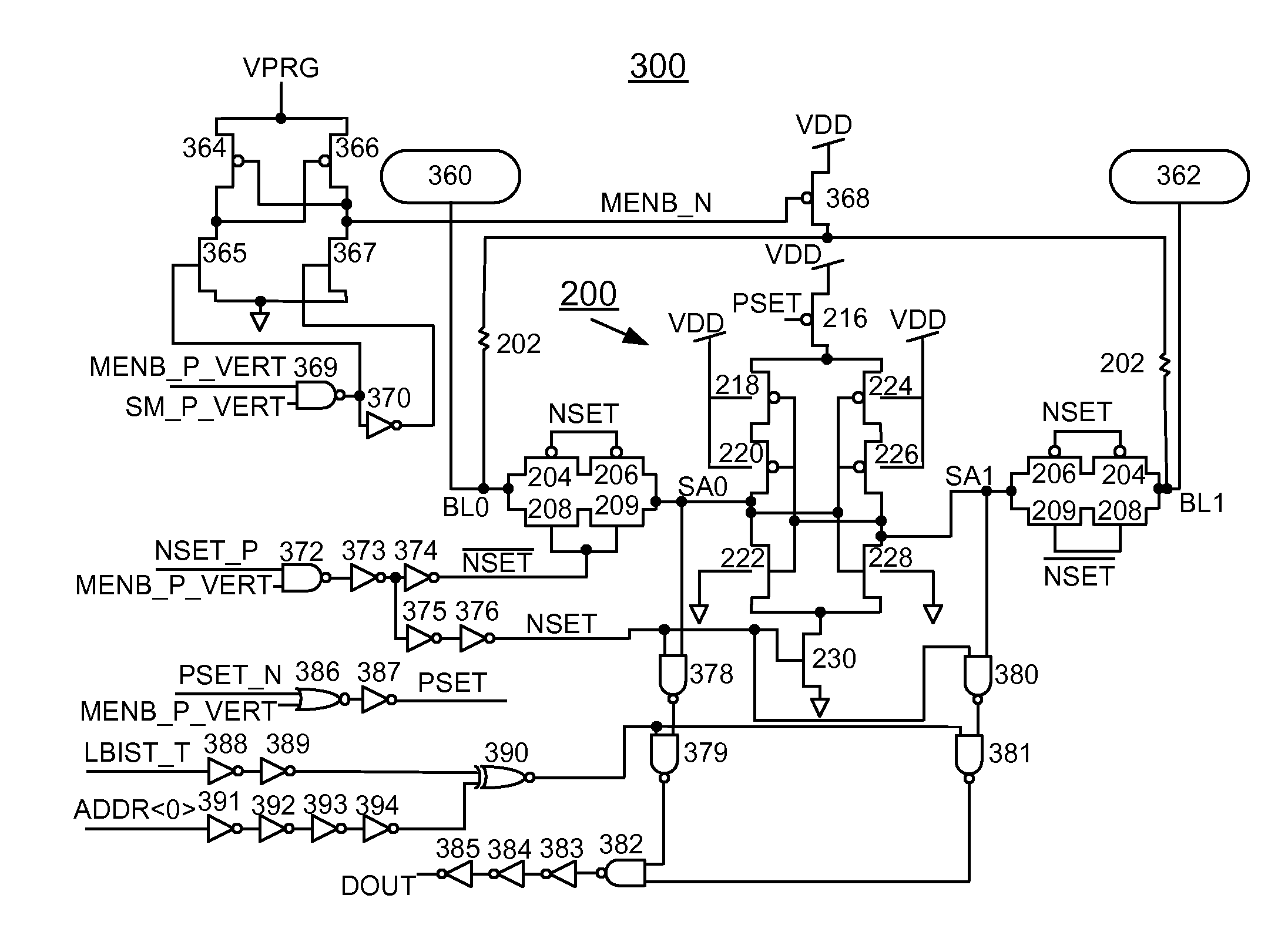
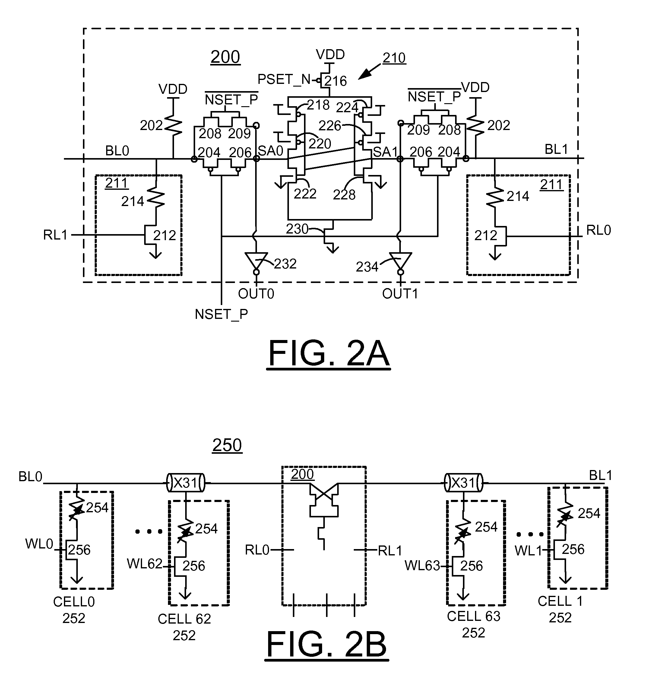
[0024]Having reference now to the drawings, in FIG. 2A, there is shown an exemplary sense amplifier generally designated by the reference character 200 in accordance with the preferred embodiment.

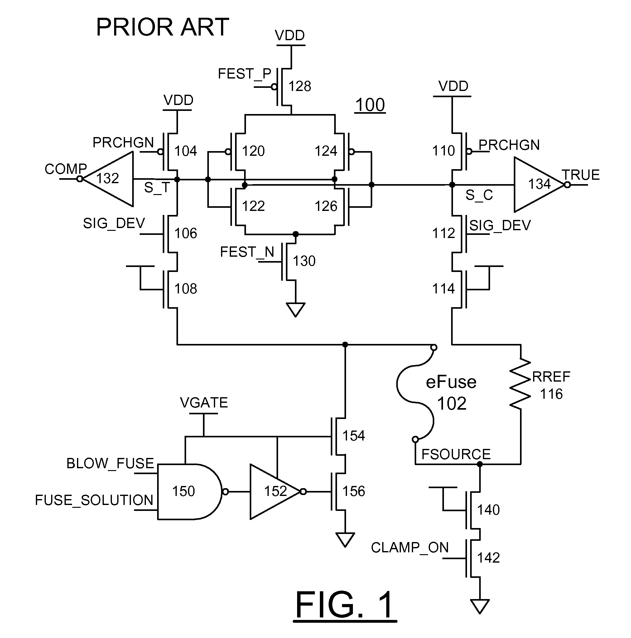
[0025]Sense amplifier 200 includes a respective pull-up resistor 202 connected between a positive voltage supply rail VDD and a respective even and odd bitline BL0, BL1. The pull-up resistors 202 replace the precharge PFETs 104, 110 of the prior art sense amplifier 100 in order to eliminate the Vt scatter, process sensitivity, and VDD sensitivity introduced by the precharge PFETs. The pull-up resistors 202 have a tighter tolerance to process variation then a PFET. The pull-up resisto...


PUM


Abstract

A method and circuit for implementing an eFuse sense amplifier, and a design structure on which the subject circuit resides are provided. A sensing circuit includes a pair of cross-coupled inverters, each formed by a pair of series connected P-channel field effect transistors (PFETs) and an N-channel field effect transistor (NFET). A first pull-up resistor is coupled between a positive voltage supply rail and a first sensing node of the sensing circuit. A second pull-up resistor is coupled between a positive voltage supply rail and a second sensing node of the sensing circuit. A first bitline is coupled to the first sensing node of the sensing circuit and a second bitline coupled to the second sensing node of the sensing circuit. One of a respective reference resistor and a respective eFuse cell is selectively coupled to the first bitline and the second bitline.

Description

FIELD OF THE INVENTION[0001]The present invention relates generally to the data processing field, and more particularly, relates to a method and circuit for implementing an enhanced eFuse sense amplifier, and a design structure on which the subject circuit resides.DESCRIPTION OF THE RELATED ART[0002]Electronic Fuses (eFuses) are currently used to configure elements after the silicon masking and fabrication process. These fuses typically are used to configure circuits for customization or to correct silicon manufacturing defects and increase manufacturing yield.[0003]In very large scale integrated (VLSI) chips, it is common to have fuses, such as eFuses that can be programmed for various reasons. Among these reasons include invoking redundant elements in memory arrays for repairing failing locations or programming identification information.[0004]As used in the following description and claims, it should be understood that the term eFuse means a non-volatile storage element that incl...

Claims


Application Information

Patent Timeline
Patent Type & Authority Patents(United States)
IPC IPC(8): G11C7/00
CPCG11C7/062G11C17/18G11C17/16G11C7/065G11C29/026
Inventor AIPPERSPACH, ANTHONY GUSPAONE, PHIL CHRISTOPHER FELICEREED, BRIAN JOYSCHMITT, DAVID EDWARDUHLMANN, GREGORY JOHN
Owner INT BUSINESS MASCH CORP
Why Eureka
Try Eureka