Imaging apparatus

a technology of image stabilization and apparatus, which is applied in the field of image stabilization apparatus, can solve the problems of increased cost, increased cost, easy failure of image stabilization means, etc., and achieve the effect of reducing the memory capacity and speeding up

Inactive Publication Date: 2010-06-01
FUJITSU LTD
View PDF11 Cites 2 Cited by
  • Summary
  • Abstract
  • Description
  • Claims
  • Application Information

AI Technical Summary

Benefits of technology

[0013]The purpose of the present invention is to provide a technique enabling a reduced memory capacity and a high speed image process in an imaging apparatus.
[0015]The present invention is contrived to compress, and retain, a plurality of images to be synthesized. A calculation of displacement amount is carried out by detecting a feature point from a thumbnail in advance, followed by decoding a zone only corresponding to the feature point detected from the thumbnail from among the compressed data. It is followed by obtaining positional information of the feature point for each piece of the compressed data by using the decoded data and calculating a displacement amount. The process for calculating the displacement amount is not required to perform for the entirety of an image and the temporarily retained data during the process are compressed data, thereby making it possible to suppress a memory capacity to be secured for calculating a displacement amount small and increase a process speed.
[0018]Furthermore, a zone decoded by the decode unit may be configured to be made up of 8M by 8N pixels (where M and N are natural numbers). In the case of compressed data being a JPEG (Joint Photographic Experts Group) format for instance, a process can be sped up by excluding extraneous processing.
[0019]The present invention enables to lower a memory capacity to be secured and speed up carrying out a process of synthesizing a plurality of images at an imaging apparatus.

Problems solved by technology

The above noted lens shift system and CCD shift system are both faced with a problem of an increased cost because hardware must be added to a camera for moving hardware such as a lens, CCD, et cetera.
Another problem associated with these methods is that means of the image stabilization is prone to a shock and easy to fail.
However, a memory capacity for storing a plurality of images tends to get larger in proportionate with digital cameras with bigger pixels, and it causing an increase of cost.
Also associated with digital cameras with bigger pixels, processes for an image stabilizer increase, hence it creates a problem of increasing the processing time.

Method used


Image

  • Imaging apparatus
  • Imaging apparatus
  • Imaging apparatus

Examples


second embodiment

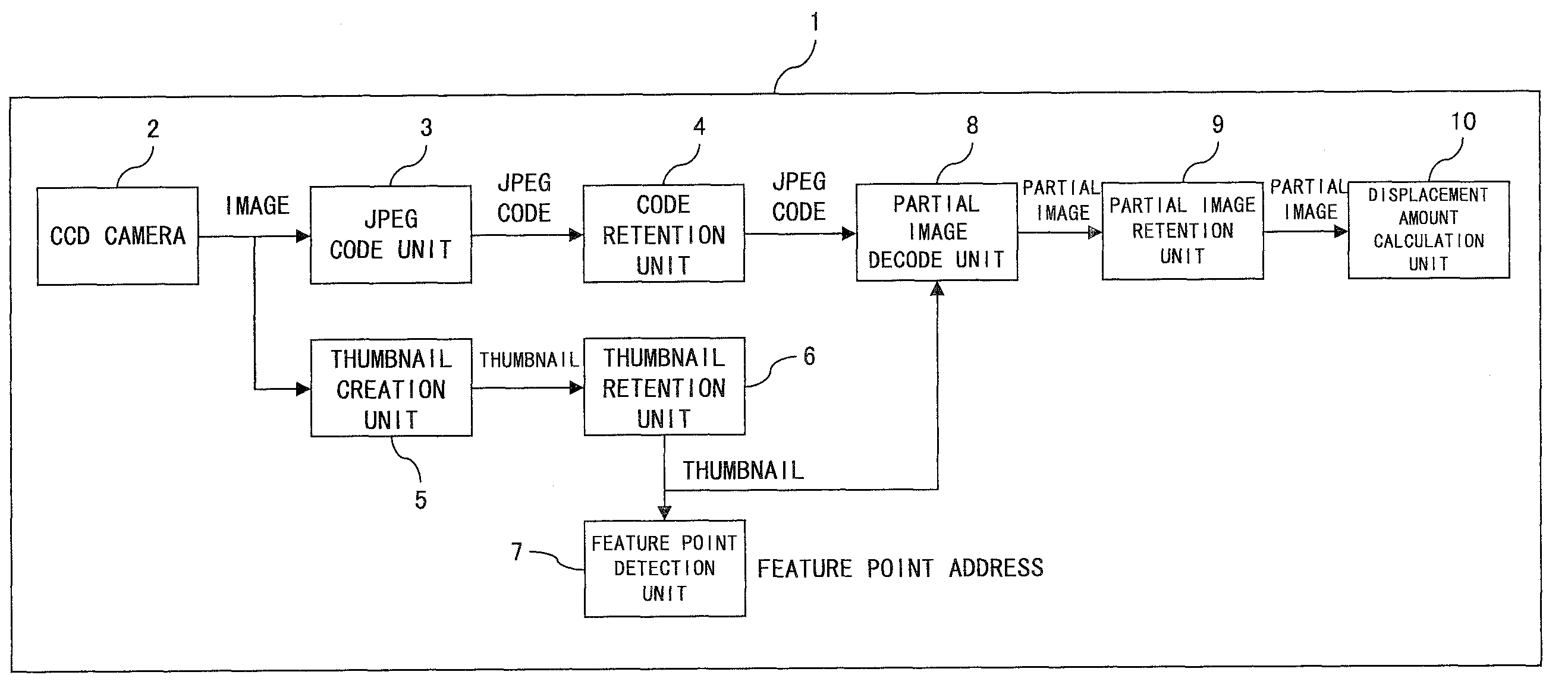
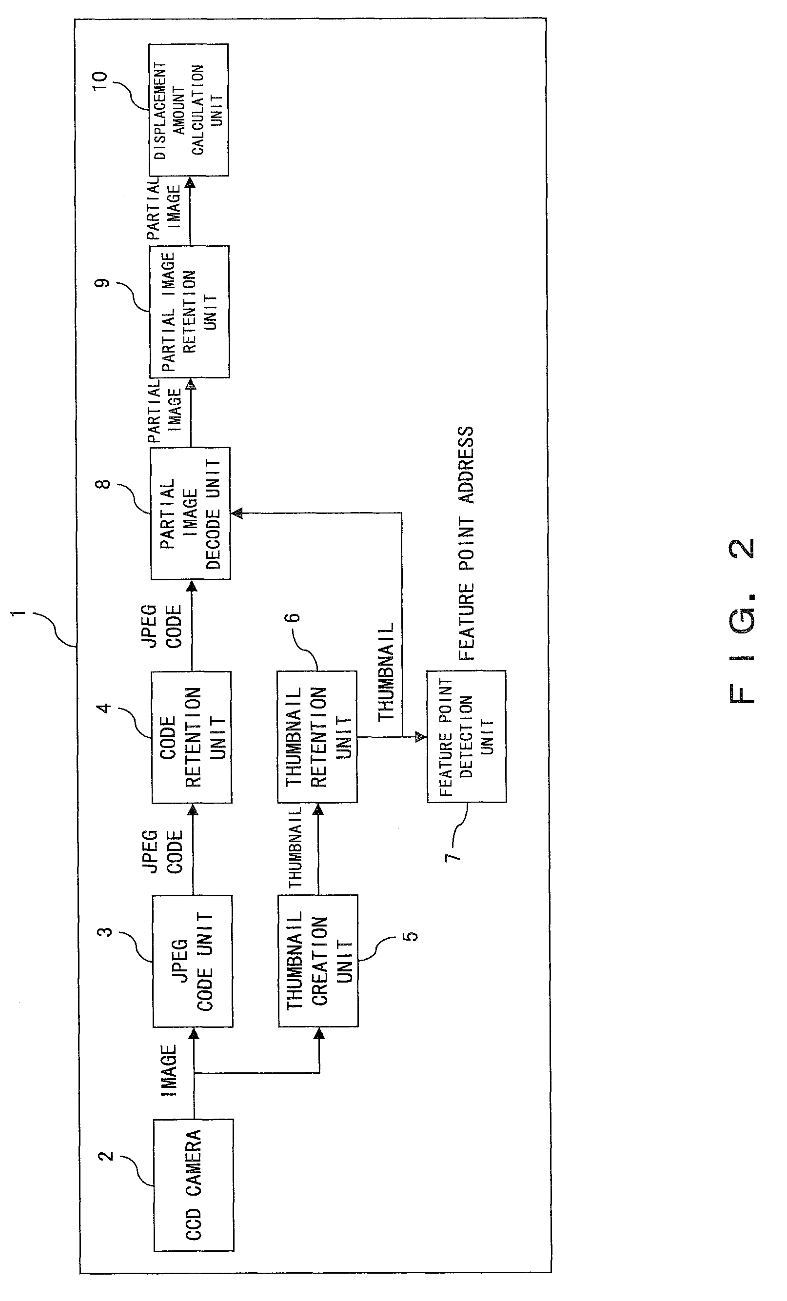
[0080]FIG. 15 is a diagram for describing data used for an image stabilization process according to a Referring to FIG. 15, the upper part represents JPEG data, that is, compressed data likewise the upper part of FIG. 7, which is the same as the above described embodiment. The lower part of FIG. 15 shows a thumbnail created for each image data obtained from the CCD camera 2.

[0081]FIG. 16 is a diagram for describing a displacement amount calculation process according to the second embodiment. It is different from the above described embodiment where the present embodiment carries out the process for detecting feature points Rn from thumbnails created for each image data.

[0082]That is, the present embodiment is configured to detect feature points Rn and Rn′ respectively from thumbnails 1 and 2 corresponding to the first and second images. It then obtains feature points Tn corresponding to the feature points Rn detected from the thumbnail 1 as for the JPEG data of the first image, and...

first embodiment

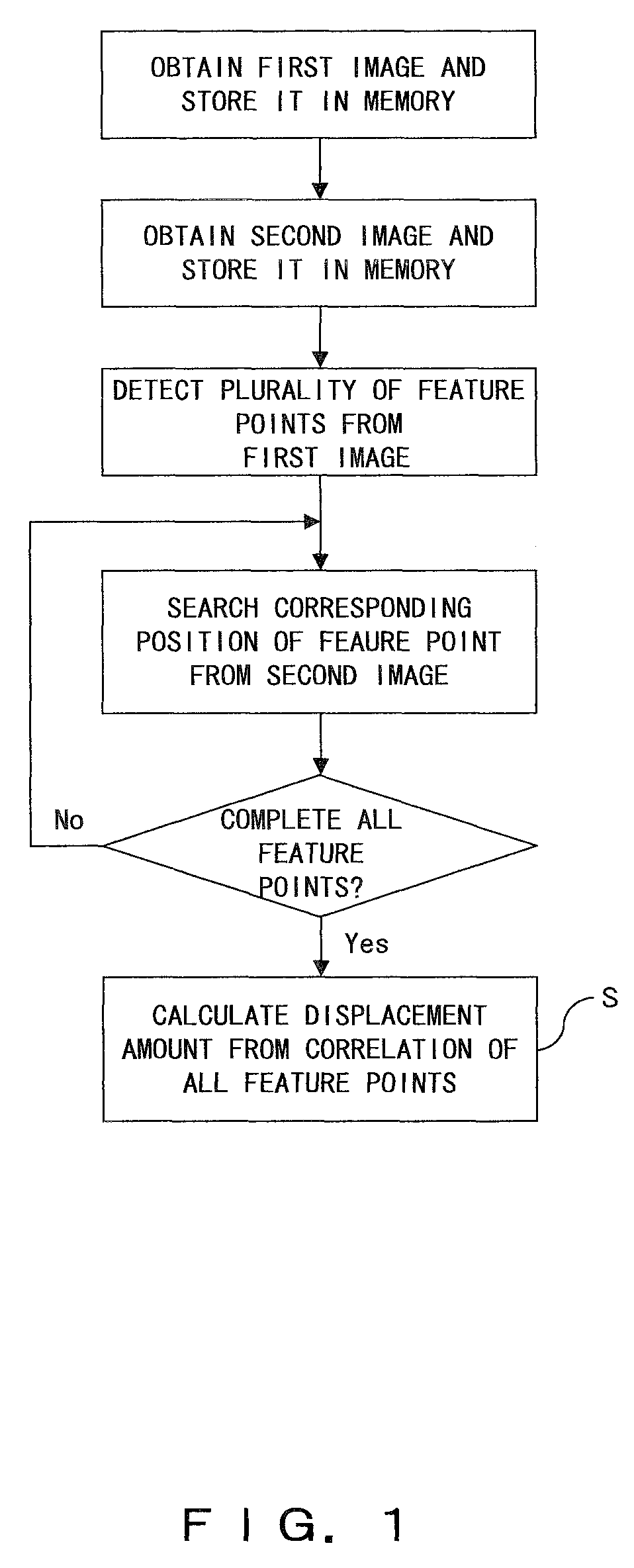
[0085]Step S45 decodes corresponding zones from respective compressed data of the first and second images based on the correlation between the feature points detected from the two thumbnails. The processes of the step S46 and thereafter respectively correspond to the processes of the step S15 and thereafter shown in FIG. 11. Note that the process for searching (i.e., the process of step S47) feature points Tn′ of the second image corresponding to the feature points Tn obtained from the first image in the step S46 is different from the process of the first embodiment where present embodiment performs the process by referring to the displacement amount obtained for the feature point Rn and Rn′ between the thumbnails in the step S44 previously.

[0086]As described above, the displacement amount calculation method according to the present second embodiment is configured to create a thumbnail for each image data and calculate, in advance, a displacement amount between the thumbnails from t...


PUM


Abstract

In an imaging apparatus, a JPEG coding unit makes JPEG data by respectively compressing plural images obtained from an imaging device. A code retention unit retains each JPEG data. A thumbnail data creation unit creates a thumbnail from each of the images. A thumbnail retention unit retains the thumbnail. A feature point detection unit detects a feature point from the thumbnail. A partial image decode unit respectively decodes zones including the feature points from each JPEG data. A displacement amount calculation unit obtains positional information of feature points in the decoded individual zones and calculates a displacement amount of each JPEG data based on the positional information.

Description

BACKGROUND OF THE INVENTION[0001]1. Field of the Invention[0002]The present invention relates to an imaging apparatus and in particular to a technique for correcting a displacement between images.[0003]2. Description of the Related Art[0004]Various techniques have conventionally been provided for correcting a displacement between images when synthesizing a plurality of static images photographed by a digital camera. A technique for correcting a displacement between images due to an unsteady camera is suitable to processing an image photographed in the dark because an exposure time required for photographing therein is longer, increasing the occurrence of an unsteady camera. Specifically, there are methods of correcting an unsteady camera (also noted as “image stabilization method” hereinafter) by means of hardware and software. The image stabilization method by means of hardware includes a lens shift system which moves lens in the direction opposite to an actual moving direction of ...

Claims


Application Information

Patent Timeline
Patent Type & Authority Patents(United States)
IPC IPC(8): G06K9/46H04N5/228
CPCH04N5/232H04N5/23229H04N5/23232H04N19/59H04N19/80H04N19/54H04N19/60H04N23/951H04N23/80
Inventor MURASHITA, KIMITAKASHIMIZU, MASAYOSHISUZUKI, SHOJIWATANABE, YASUTO
Owner FUJITSU LTD
Why Eureka
Try Eureka