
Optical fiber provided with reliable coating layers

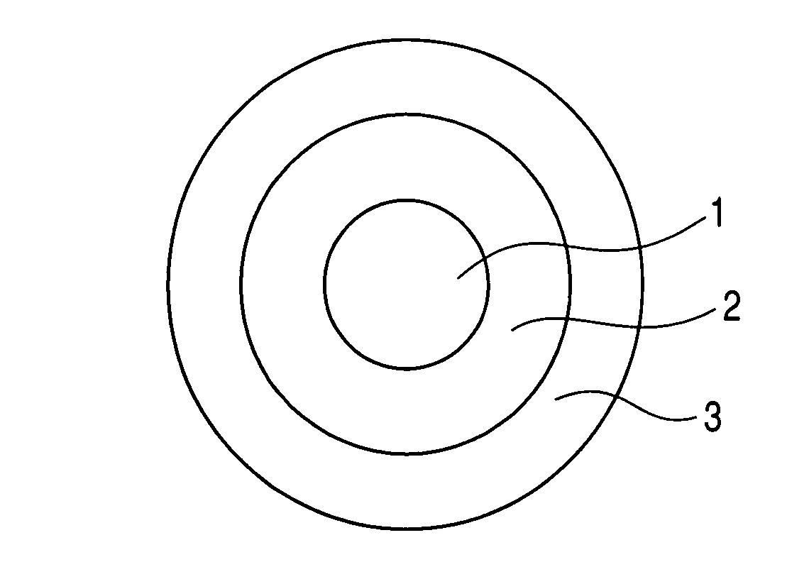
a technology of optical fiber and coating layer, applied in the field of optical fiber, can solve the problems of ineffective prevention of loss increase, limitation in ensuring sufficient adhesiveness, increase in transmission loss, etc., and achieve the effect of suppressing the increase in transmission loss due to microbending, preventing delamination, and excellent long-term reliability

Active Publication Date: 2010-06-01
FURUKAWA ELECTRIC CO LTD
View PDF21 Cites 9 Cited by
  • Summary
  • Abstract
  • Description
  • Claims
  • Application Information

AI Technical Summary

Benefits of technology

This design effectively suppresses delamination and transmission loss even when immersed in water, ensuring high reliability and performance of the optical fiber as a transmission line.

Problems solved by technology

If case such delamination is caused, uneven force acts on the glass optical fiber induced by the delamination to cause microbending, whereby the transmission loss is increased.
However, there is a limitation in ensuring such sufficient adhesiveness while maintaining the function of each of the coating layers.
However, this method cannot be an effective measure for preventing the increase in the loss due to the occurrence of microbending which is caused at the time when water reaches the optical fiber under the usage environment mentioned above.
Even the method described in Patent Document 2 cannot completely shut out water that reaches the optical fiber, and thus the loss due to microbending unavoidably increases depending on the usage environment.
Thus, under the present circumstances, there is no extremely effective measure for suppressing the loss increase when an optical fiber is immersed in water.

Method used


Image

  • Optical fiber provided with reliable coating layers
  • Optical fiber provided with reliable coating layers
  • Optical fiber provided with reliable coating layers

Examples


examples

[0038]In the optical fiber described above and having a structure shown in FIG. 1, the relaxation modulus of the secondary coating layer 3 was varied and the additive amount of the silane coupling agent was varied to prepare optical fibers corresponding to the Examples of the present invention and those for Comparative Examples. It should be noted that γ-mercaptopropyltrimethoxysilane was used as the silane coupling agent. This is shown in Table 1.

[0039]It should also be noted that the optical fiber was a standard single-mode optical fiber with the glass optical fiber having an outer diameter of about 125 μm, the primary coating layer having an outer diameter of about 195 μm and the secondary coating layer having an outer diameter of about 245 μm.

[0040]Further, as the primary coating layer, several types of 0.2-mm cured sheets of urethane-acrylate base UV resins with Young's modulus of 1.0 MPa were used. As the secondary coating layer, 0.2-mm cured sheets of urethane-acrylate base U...


PUM

PropertyMeasurementUnit
Young's modulusaaaaaaaaaa
temperatureaaaaaaaaaa

Abstract

An optical fiber is provided, which is unlikely to cause interlayer delamination between a glass optical fiber and a primary coating layer even when it is immersed in water. The optical fiber of the present invention includes a glass optical fiber 1 consisting of a core and a cladding, a primary coating layer 2 overlaid on the glass optical fiber, and a secondary coating layer 3 overlaid on the primary coating layer, wherein the relaxation modulus of the secondary coating layer is set at 400 MPa or less.

Description

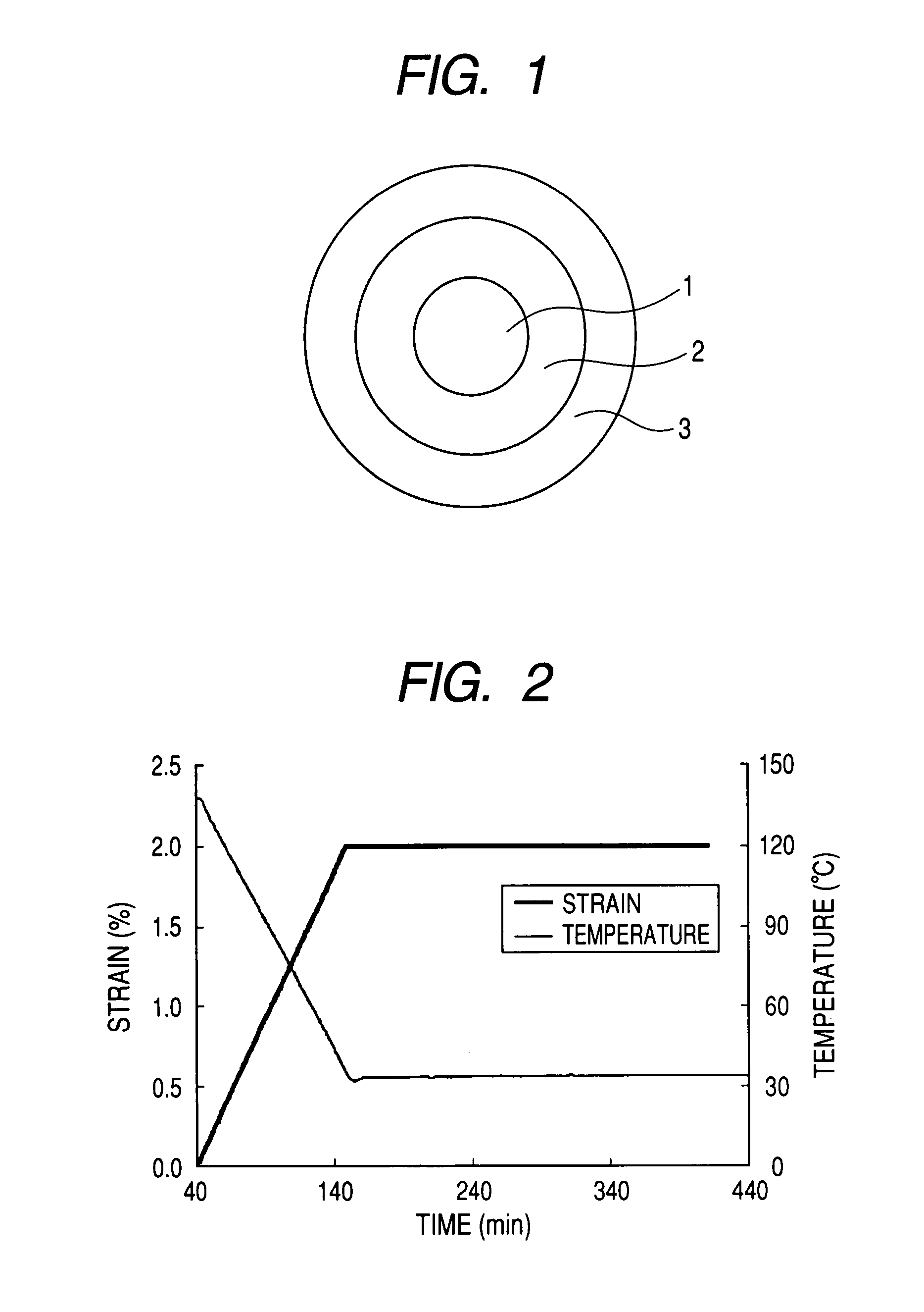
FIELD OF THE INVENTION[0001]The present invention relates to an optical fiber for transmitting optical signals having highly reliable coating layers.BACKGROUND ART[0002]Conventional optical fibers generally have a structure, as shown in FIG. 1, in which a soft primary coating layer 2 is overlaid on a glass optical fiber 1 consisting of silica glass having a core and a cladding which is provided outside the core, and a hard secondary coating layer 3 is further overlaid on the primary coating layer 2.[0003]Typically, a UV curable resin having Young's modulus of 3 MPa or less has been used as the primary coating layer 2, and a UV curable resin having Young's modulus of 500 MPa or more has been used as the secondary coating layer 3.[0004]When such an optical fiber ribbon is immersed in water, delamination may occur at an interface between the glass optical fiber 1 and the primary coating layer 2[0005]If case such delamination is caused, uneven force acts on the glass optical fiber induc...

Claims


Application Information

Patent Timeline
Patent Type & Authority Patents(United States)
IPC IPC(8): G02F1/01G02B6/02
CPCC03C25/106G02B6/02395C03C25/1065
Inventor NAKAJIMA, YASUOTANAKA, HIROKIARASHITANI, YOSHIHIROONO, TAKAYOSHI
Owner FURUKAWA ELECTRIC CO LTD
Learn More