Micro coated electrical feedthru

a technology of micro coating and feedthru, which is applied in the direction of electrical apparatus casings/cabinets/drawers, hermetically sealed casings, coupling device connections, etc., can solve the problems of limiting the performance of feedthrough, using dissimilar materials for the construction of feedthru, and limiting the range of typical electrical feedthrus, etc., to facilitate the construction of more transmission lines. , the effect of high pin density

Inactive Publication Date: 2006-11-02
SCHLUMBERGER TECH CORP
View PDF26 Cites 2 Cited by
  • Summary
  • Abstract
  • Description
  • Claims
  • Application Information

AI Technical Summary

Benefits of technology

[0008] Another embodiment of the present invention provides an electrical feedthru with a transmission line density of at least 0.4 pins per mm2. The density may also be at least 0.8 transmission lines per mm2 according to other embodiments. A high pin density facilitates more transmission lines in smaller packages.

Problems solved by technology

However, these standard electrical feedthrus have a number of drawbacks.
The primary problem associated with standard electrical feedthrus is the use of dissimilar materials for construction of the feedthru.
Therefore, to maintain the integrity of the seal between the ceramic and the metal, typical electrical feedthrus are limited to a relatively narrow range of temperatures and pressure fluctuations.
High stresses at the interface (9) result in feedthrus that are prone to failure, and thus limit the performance of the feedthrough.
Another problem associated with electrical feedthrus is the size.
Standard electrical feedthrus are often much too large for many applications, particularly for micro-electro-mechanical-systems (MEMS).
Further, as the number of transmission lines needed increases, the size of the electrical feedhthrus or bulkheads becomes even larger.
Yet another disadvantage of typical electrical feedthrus is the inability of ceramic, glass, and epoxy material to conduct heat.
Poor heat conduction means limited ability to dissipate heat.
Therefore, typical electrical feedthrus such as the feedthru (2) shown in FIG. 1 are not capable of efficiently dissipating heat through the body (6).

Method used


Image

  • Micro coated electrical feedthru
  • Micro coated electrical feedthru
  • Micro coated electrical feedthru

Examples


Embodiment Construction

[0026] Illustrative embodiments and aspects of the invention are described below. In the interest of clarity, not all features of an actual implementation are described in this specification. It will of course be appreciated that in the development of any such actual embodiment, numerous implementation-specific decisions must be made to achieve the developers' specific goals, such as compliance with system-related and business-related constraints, that will vary from one implementation to another. Moreover, it will be appreciated that such a development effort might be complex and time-consuming, but would nevertheless be a routine undertaking for those of ordinary skill in the art having the benefit of this disclosure.

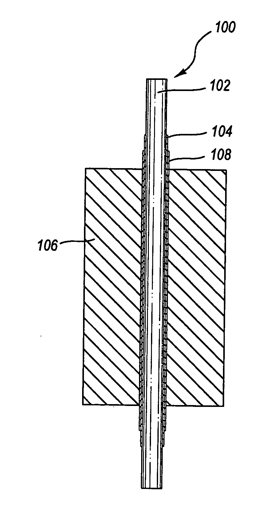
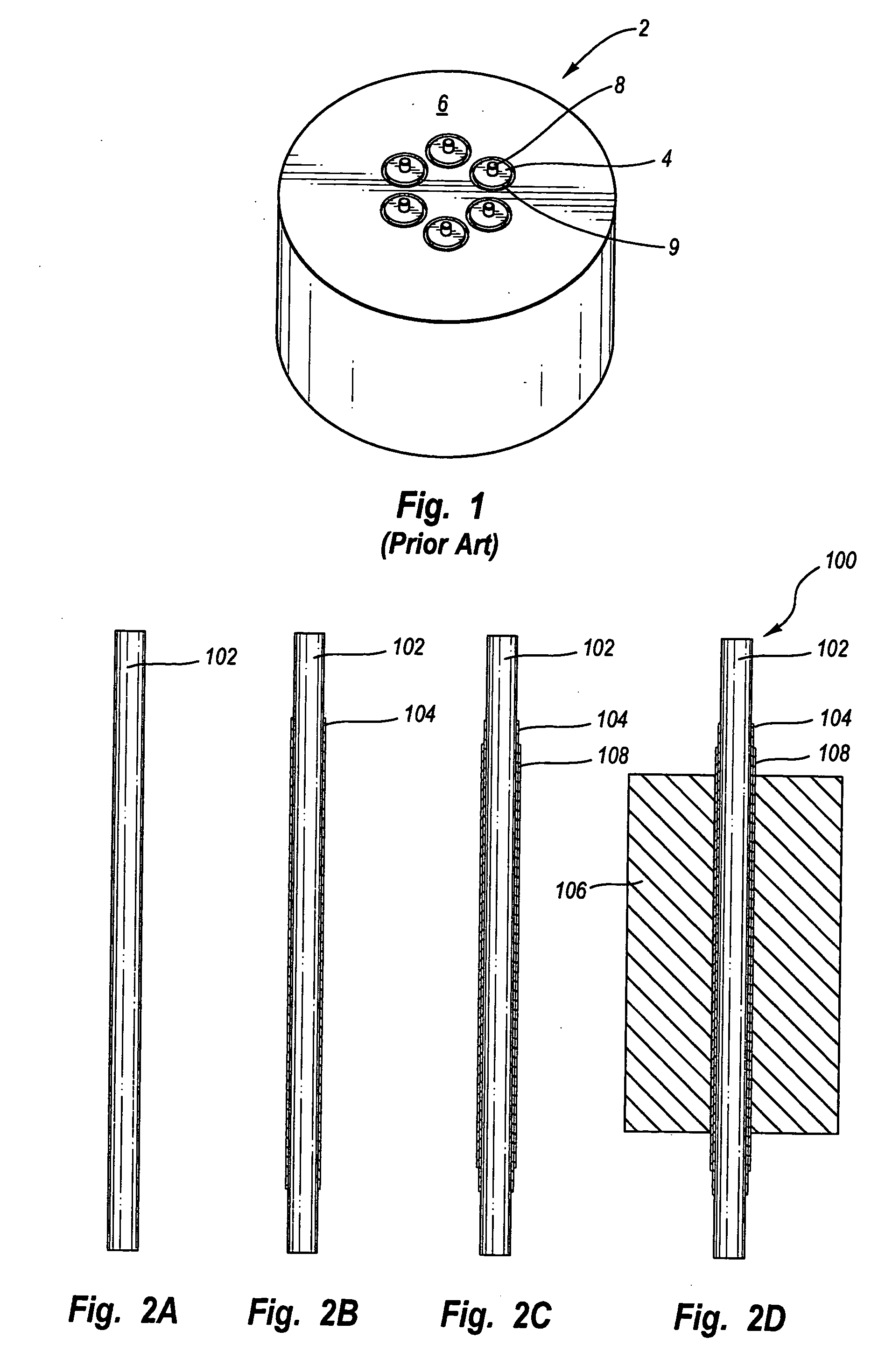
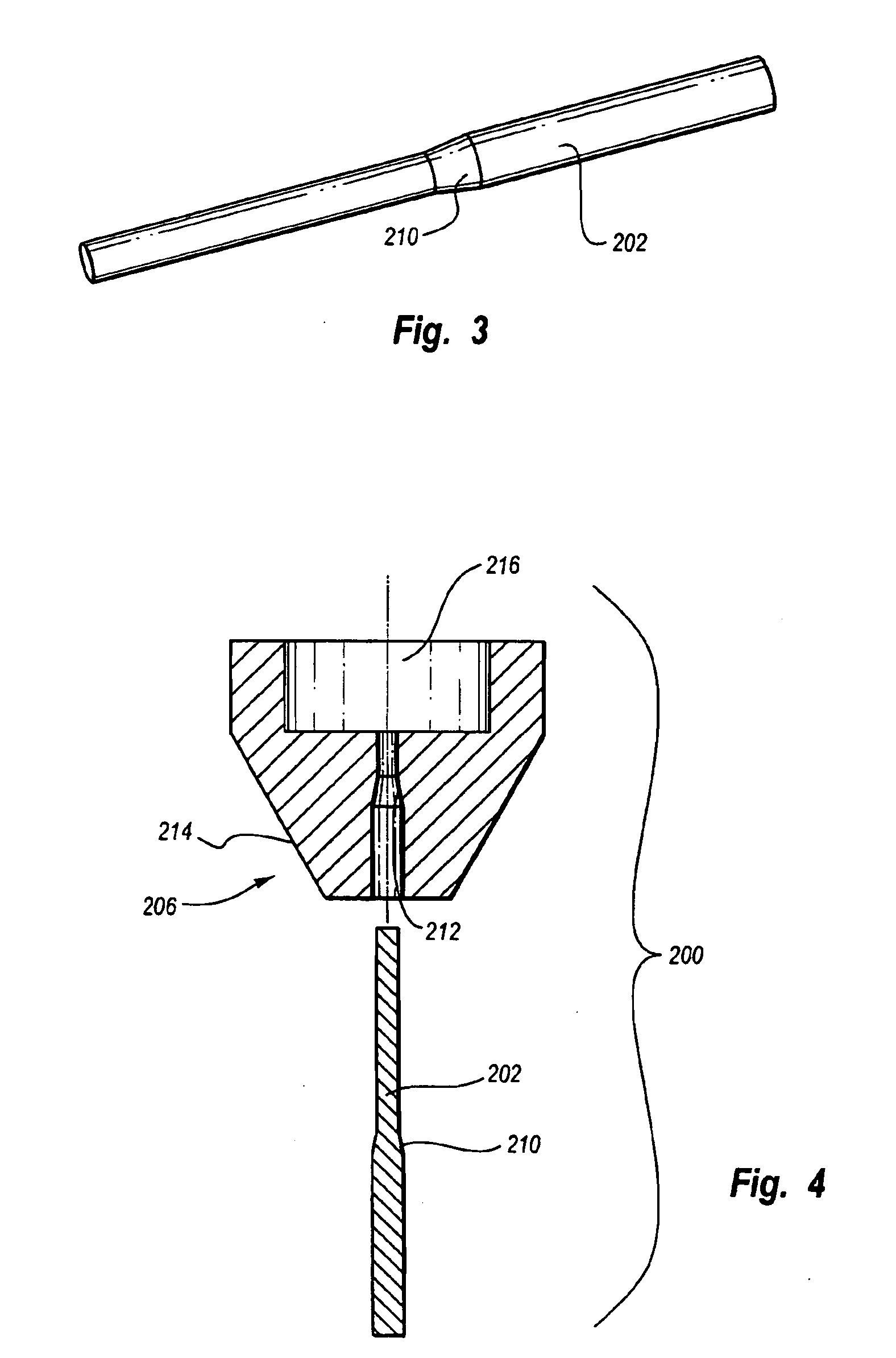
[0027] The present invention contemplates methods and apparatus for transmitting electrical signals, power transmission, or both between two or more distinct environments. As mentioned in the background, devices used for electrical transmission across two or more dis...


PUM

PropertyMeasurementUnit
diameteraaaaaaaaaa
diameteraaaaaaaaaa
diameteraaaaaaaaaa

Abstract

A method and apparatus for electrically interfacing between two or more distinct environments. The method and apparatus are directed to an electrical feedthru with one or more electrical transmission lines coated with one or more thin dielectric layers of material to insulate the transmission lines from a feedthru body. The dielectric layers may include a diamond-like carbon coating, which electrically insulates, but also thermally conducts. The use of thin dielectric layers facilitates smaller, more efficient electrical feedthrus. Therefore, the electrical feedthru may be used, for example, with MEMS devices. The electrical feedthru is not limited to any particular geometry, it may be adapted to fit between any two environments.

Description

FIELD OF THE INVENTION [0001] The present invention relates generally to methods and apparatus for transmitting electrical signals, power, or both. More particularly, the present invention relates to transmitting electrical signals, power, or both across two or more distinct environments. BACKGROUND OF THE INVENTION [0002] A variety of standard methods and devices currently exist for passing electrical signals and current across distinct environments. Such devices are commonly referred to as electrical feedthrus or bulkheads. The intent of electrical feedthrus is to facilitate passage of the electrical signals, current, or both across the distinct environments without breaching the integrity of any boundary between the two distinct environments. One variety of electrical feedthrus includes epoxy encapsulated transmission lines. The transmission lines are usually centered within the epoxy capsule, with the lines running parallel to the epoxy capsule. The epoxy capsule insulates the t...

Claims


Application Information

Patent Timeline
Patent Type & Authority Applications(United States)
IPC IPC(8): H01R13/40H01B17/30H01R13/648H02G3/22
CPCH01B17/306Y10T428/30Y10S439/935H02G3/22
Inventor SHAH, JAGDISH
Owner SCHLUMBERGER TECH CORP
Why Eureka
Try Eureka