Modular disc cutterbar

a cutterbar and module technology, applied in the direction of mowers, agriculture tools and machines, mowers, etc., can solve the problems of cutterhead damage or cutterhead driveline damag

Active Publication Date: 2010-06-08
BLUE LEAF I P INC
View PDF18 Cites 15 Cited by
  • Summary
  • Abstract
  • Description
  • Claims
  • Application Information

AI Technical Summary

Benefits of technology

[0005]Accordingly, the present invention, in any of the embodiments described herein, may provide one or more of the following advantages:
[0006]It is an object of the present invention to provide a cutterhead module mount for a header that enables an individual module to be removed without disassembling a majority of the cutterhead modules from the cutterbar.
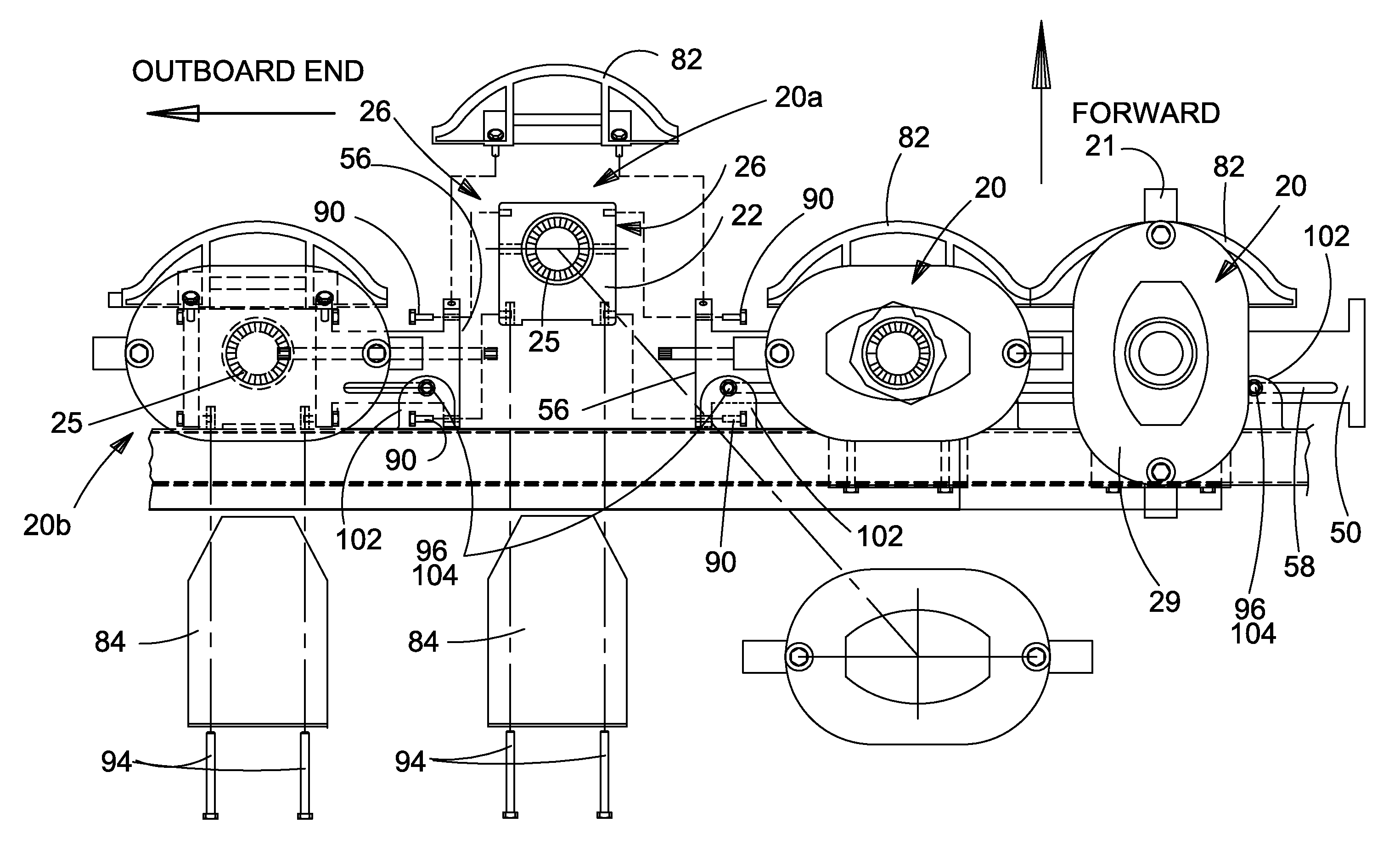
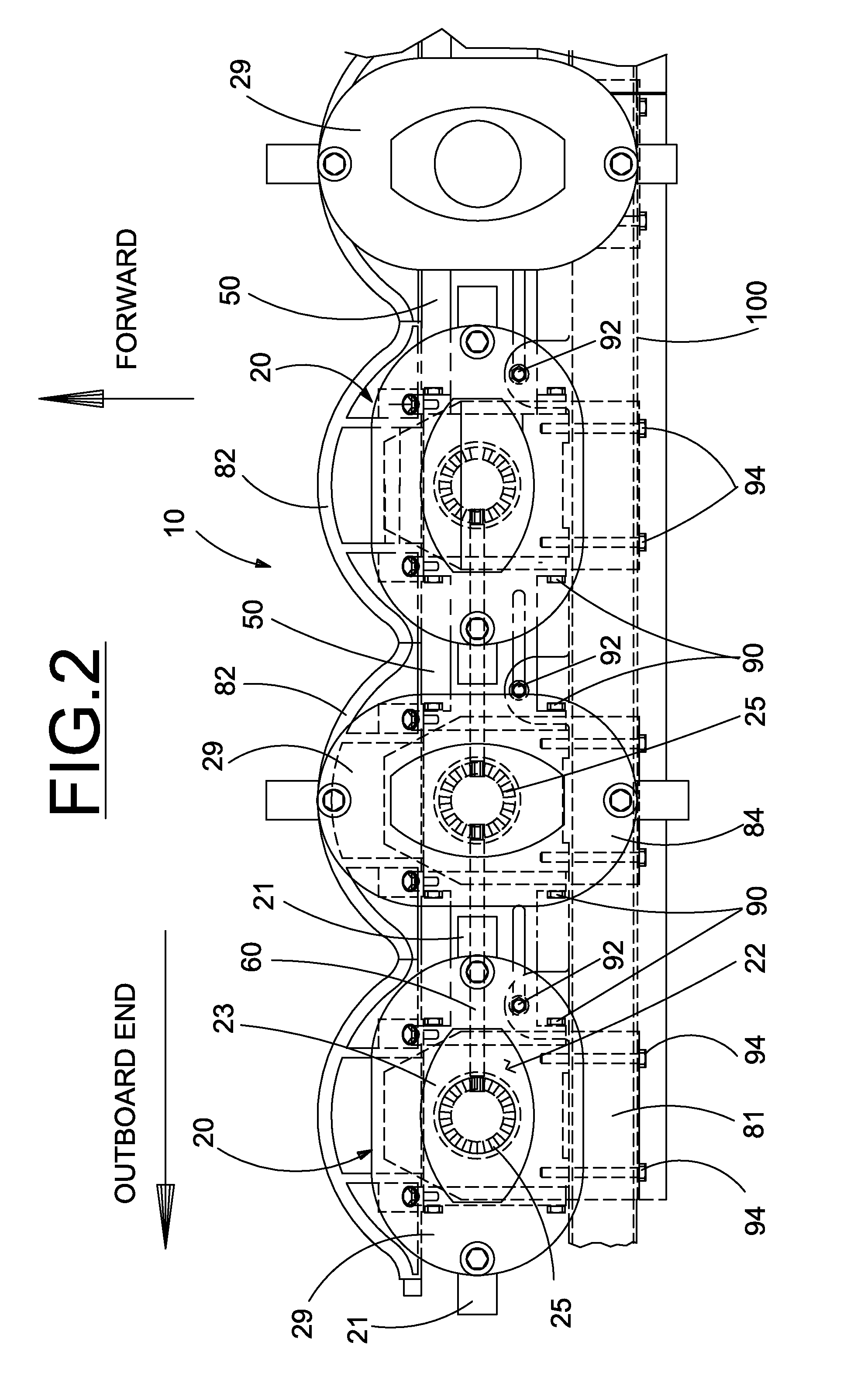
[0007]It is a further object of the present invention to provide a cutterhead module mounting configuration that enables modules and connecting spacers to be laterally displaced sufficiently to enable a failed cutterhead module to be removed without disassembling the adjacent cutterhead and spacer modules.
[0008]It is a further object of the present invention to provide a cutterhead module mounting configuration that supports all of the cutterhead modules while a failed module is removed and replaced thereby reducing the need for additional temporary module supports during the operation and improving safety during the operation.
[0009]It is a still further object of the present invention to provide an improved structure for mounting modular disc cutters on a header in a manner that enables easier removal and replacement of a damaged module that is durable in construction, inexpensive of manufacture, carefree of maintenance, easily assembled, and simple and effective to use.
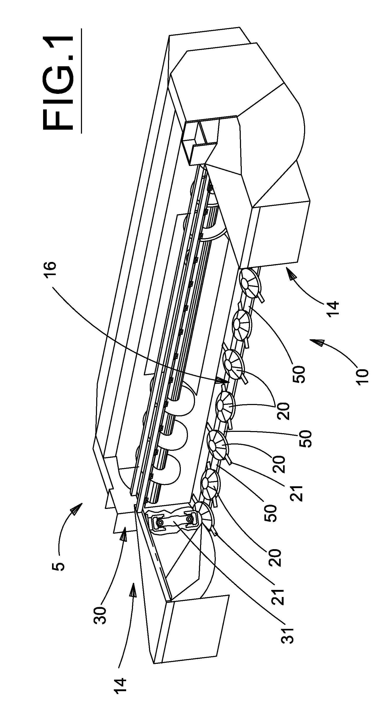
[0010]These and other objects are achieved in accordance with the instant invention by providing an improved disc cutter module mounting structure for an agricultural header that enables one or more disc cutter modules and interconnection spacers to be temporarily laterally displaced a distance sufficient to disengage the transverse drive apparatus from a failed module thereby allowing the failed module to be removed from the header for repair or replacement. The laterally displaced modules and spacers need only be disconnected from the outboard drive shaft; lateral displacement is accomplished by the incorporation of slotted mounting guides on the spacers and a plurality of spaced-apart support tabs on the header frame. The improved mounting structure also supports the modules and spacers during the removal / replacement process reducing the need for jacks to support modules as they are being repositioned on the header.

Problems solved by technology

Cutterbars frequently impact rocks and other obstructions in a field which can damage the cutterhead or the cutterhead driveline.
However, replacing a single damaged cutterhead module is not an insignificant task requiring significant disassembly of the cutter bar in order to remove a damaged cutterhead from the cutterbar driveline because of intermediate drive shafts disposed between adjacent modules to transfer power laterally along the cutterbar.

Method used


Image

  • Modular disc cutterbar
  • Modular disc cutterbar
  • Modular disc cutterbar

Examples


Embodiment Construction

)

[0016]Many of the fastening, connection, processes and other means and components utilized in this invention are widely known and used in the field of the invention described, and their exact nature or type is not necessary for an understanding and use of the invention by a person skilled in the art, and they will not therefore be discussed in significant detail. Also, any reference herein to the terms “left” or “right” are used as a matter of mere convenience, and are determined by standing at the rear of the machine facing in its normal direction of travel. Likewise, “forward” and “rearward” are determined by the normal direction of travel. “Upward” and “downward” orientations are relative to the ground or operating surface as are any references to “horizontal” or “vertical” planes. Furthermore, the various components shown or described herein for any specific application of this invention can be varied or altered as anticipated by this invention and the practice of a specific ap...


PUM


Abstract

A disc cutter module mounting structure for an agricultural header that enables one or more disc cutter modules and interconnection spacers to be temporarily laterally displaced a distance sufficient to disengage the transverse drive apparatus from a failed module thereby allowing the failed module to be removed from the header for repair or replacement. The laterally displaced modules and spacers need only be disconnected from the outboard drive shaft; lateral displacement is accomplished by the incorporation of slotted mounting guides on the spacers and a plurality of spaced-apart support tabs on the header frame. The mounting structure also supports the modules and spacers during the removal / replacement process reducing the need for jacks to support modules as they are being repositioned on the header.

Description

BACKGROUND OF THE INVENTION[0001]This invention relates generally to a machine for severing standing crops from the ground to initiate a harvesting process and, more particularly, to a rotary disc cutterbar having a preselected number of transversely oriented, rotatable discs having knives mounted thereon to sever standing crop by an impact action upon rotation of the discs.[0002]Typical disc cutterbars used in agriculture include an elongated housing containing a train of meshed idler and drive spur gears, or a main power shaft or series of power shafts coupled by respective bevel gear sets, for delivering power to respective drive shafts for modular cutterheads spaced along the length of the cutterbar. The cutterheads each comprise a cutting disc including diametrically opposed cutting blades (though configurations with three or more blades are known) and having a hub coupled to an upper end of a drive shaft, the lower end of the drive shaft carrying a spur gear in the case where ...

Claims


Application Information

Patent Timeline
Patent Type & Authority Patents(United States)
IPC IPC(8): A01D34/00
CPCA01D34/665
Inventor EHRHART, PHILIP J.OSBORNE, DONALD L.DECHRISTOPHER, DAVID M.
Owner BLUE LEAF I P INC
Why Eureka
Try Eureka