High pressure valve for hydrogen gas and decompression device for hydrogen gas

a technology of hydrogen gas and decompression device, which is applied in the direction of fluid pressure control, container discharge methods, instruments, etc., can solve the problem of inability to maintain sufficient sealing effectiveness, and achieve the effect of sufficient sealing effectiveness

Inactive Publication Date: 2010-06-08
TOYOOKI KOGYO CO LTD +1
View PDF50 Cites 22 Cited by
  • Summary
  • Abstract
  • Description
  • Claims
  • Application Information

AI Technical Summary

Benefits of technology

[0007]Accordingly, it is an objective of the present invention to provide a high pressure valve for hydrogen gas and a decompression device for hydrogen gas that provide sufficient sealing effectiveness even if the pressure of the hydrogen gas is increased.

Problems solved by technology

Therefore, if the prior art electromagnetic valve and the pressure reducing valve are actually used in the tank for hydrogen gas having higher pressure, sufficient sealing effectiveness cannot be maintained.

Method used


Image

  • High pressure valve for hydrogen gas and decompression device for hydrogen gas
  • High pressure valve for hydrogen gas and decompression device for hydrogen gas
  • High pressure valve for hydrogen gas and decompression device for hydrogen gas

Examples


Embodiment Construction

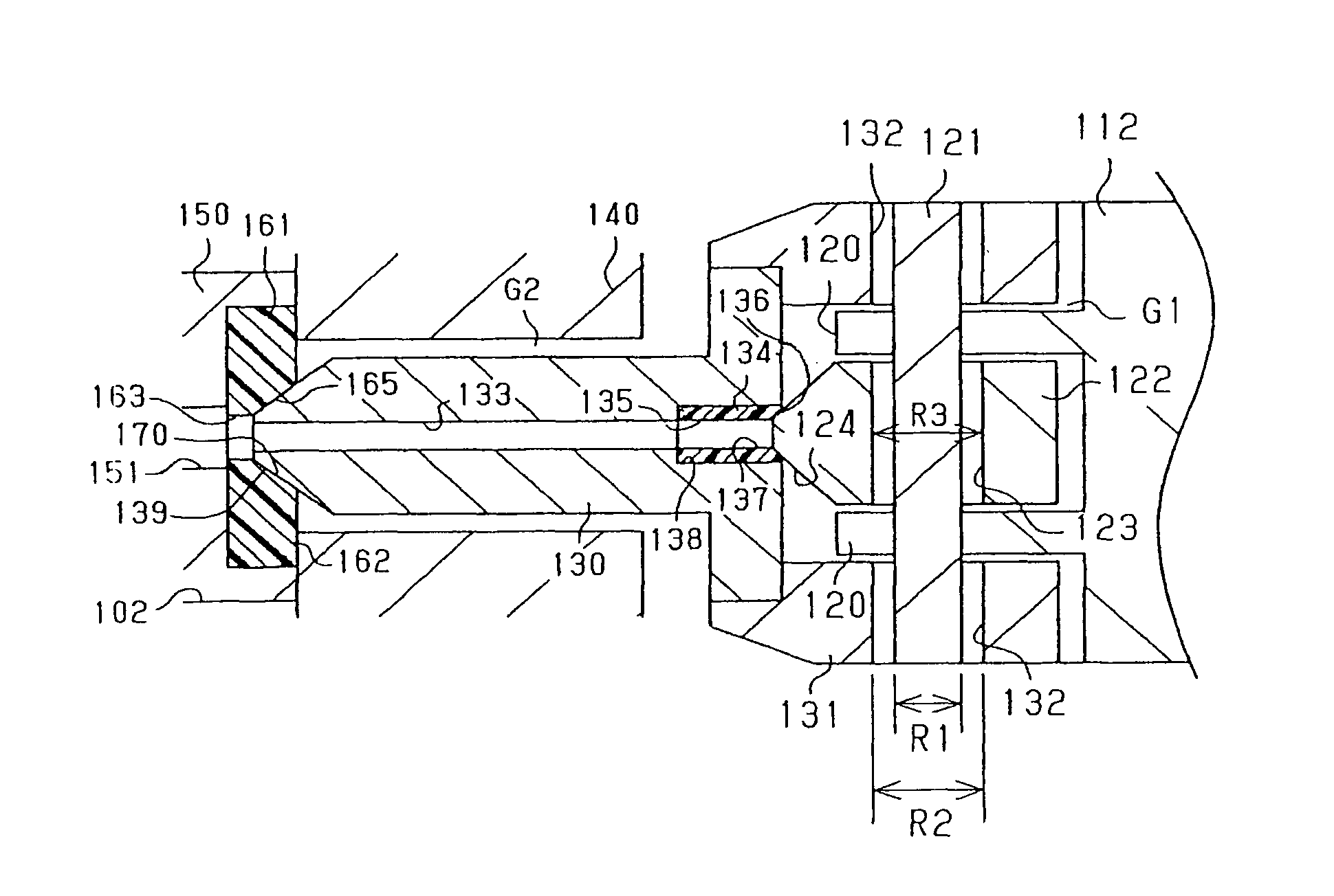
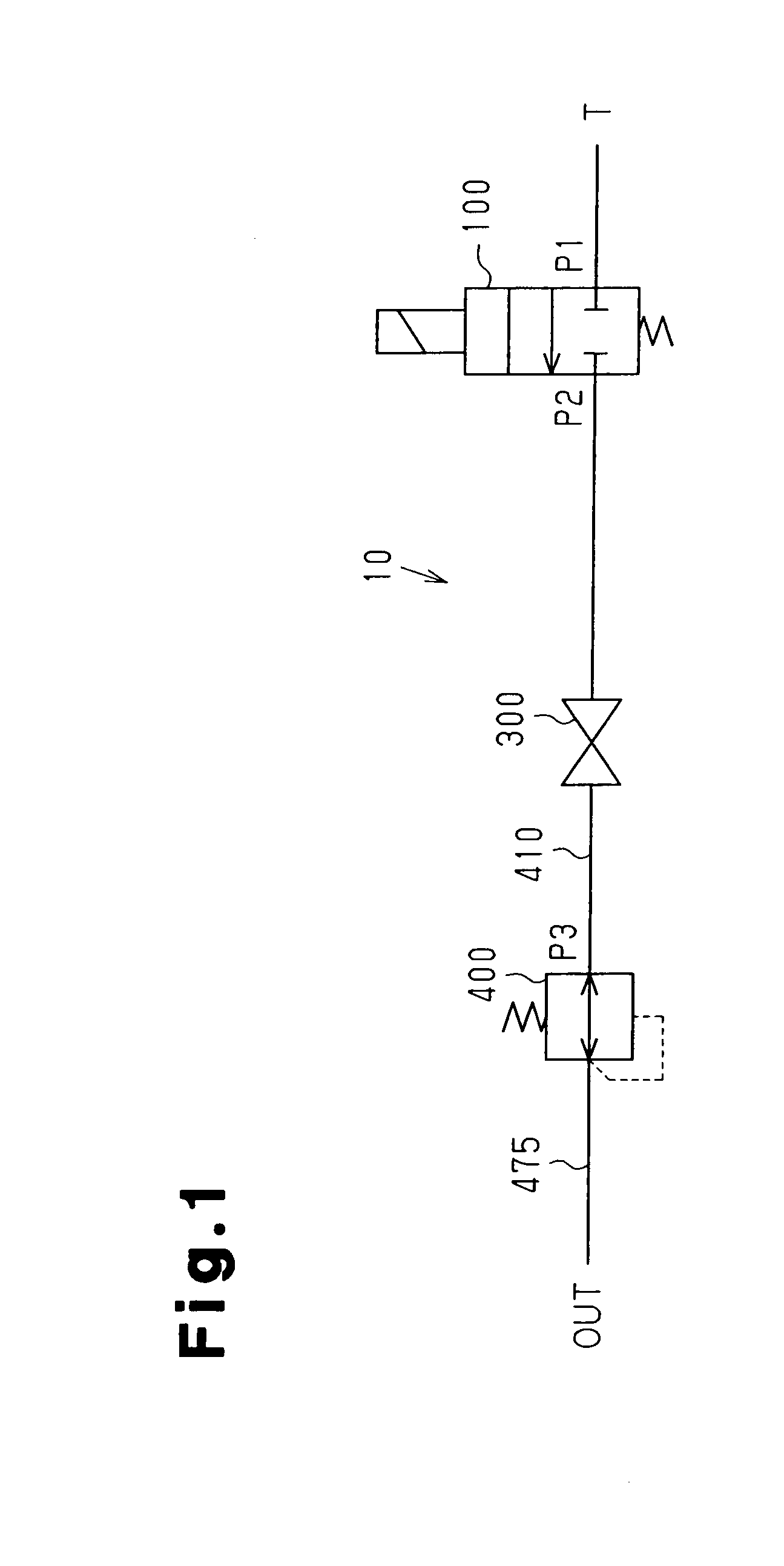
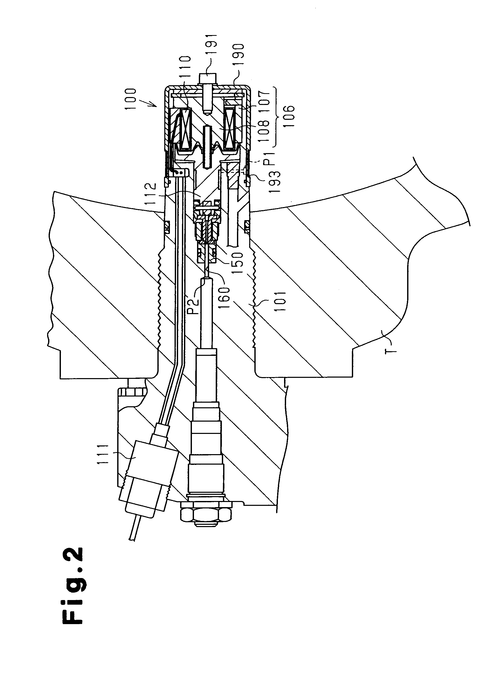
[0024]A high pressure valve for hydrogen gas and a decompression device 10 for hydrogen gas (hereinafter, referred to as a decompression device) according to one embodiment of the present invention will now be described with reference to FIGS. 1 to 6. The high pressure valve for hydrogen gas is applied to an electromagnetic valve 100 and a pressure reducing valve 400. The decompression device includes the electromagnetic valve 100 and the pressure reducing valve 400.

[0025]The decompression device 10 shown in FIG. 1 is mounted to a high-pressure hydrogen gas container, which is a high-pressure hydrogen tank T in this embodiment. The tank T is filled with hydrogen gas at a high pressure (70 MPa in this embodiment). The decompression device 10 includes an electromagnetic valve 100, a stop valve 300, and a pressure reducing valve 400. A stop valve 300 is open when high-pressure hydrogen gas is used.

[0026]When the electromagnetic valve 100 is open, high-pressure hydrogen gas in the tank ...


PUM

PropertyMeasurementUnit
pressureaaaaaaaaaa
pressureaaaaaaaaaa
pressureaaaaaaaaaa

Abstract

A high pressure valve for hydrogen gas includes a valve seat and a valve member, which is movable to selectively open and close the valve seat. One of the valve member and the valve seat is formed of austenitic stainless steel, and the other one of the valve member and the valve seat is formed of flexible synthetic resin or soft metal.

Description

[0001]The present application is a divisional application of U.S. patent application Ser. No. 10 / 878,613 filed on Jun. 29, 2004, and is based on Japanese patent application No. 2003-188589 filed Jun. 30, 2003, which is hereby incorporated herein by reference.BACKGROUND OF THE INVENTION[0002]The present invention relates to a high pressure valve for hydrogen gas and a decompression device for hydrogen gas. More particularly, the present invention pertains to a high pressure valve for hydrogen gas and a decompression device for hydrogen gas that are suitable for use in a high-pressure hydrogen gas tank for automobiles driven by a fuel cell.[0003]In the prior art, a high-pressure hydrogen gas tank for an automobile driven by a fuel cell is filled with hydrogen gas at a pressure of 35 MPa. As for a high pressure valve for hydrogen gas attached to the high-pressure hydrogen gas tank, for example, an electromagnetic valve or a pressure reducing valve is used. The pressure reducing valve r...

Claims


Application Information

Patent Timeline
Patent Type & Authority Patents(United States)
IPC IPC(8): G05D16/06F16K1/34F16K31/06F17C13/04H01M8/04
CPCF17C13/04Y02E60/321F17C2205/0326F17C2205/0382F17C2270/0184F17C2223/0123F17C2223/035F17C2223/036F17C2270/0168F17C2221/012Y02E60/32Y10T137/7761Y10T137/7762Y10T137/86984Y10T137/87917
Inventor SUZUKI, HIROAKITAKEUCHI, YOSHIYUKISHIMA, TOSHIHIKOSHIRAI, SOICHI
Owner TOYOOKI KOGYO CO LTD
Why Eureka
Try Eureka