Apparatus and method for performing counts within a biologic fluid sample

a technology apparatus, which is applied in the field of chambers for analyzing biologic fluids, can solve the problems of preventing the accurate initial measurement or later calculation of sample quantity, and achieves the effects of high mobility, low cost, and simple structur

Active Publication Date: 2010-06-08
WARDLAW PARTNERS +2
View PDF29 Cites 62 Cited by
  • Summary
  • Abstract
  • Description
  • Claims
  • Application Information

AI Technical Summary

Benefits of technology

[0011]A method and apparatus for counting elements within a fluid medium is provided that is simple, accurate and relatively low cost. The method and apparatus is particularly well suited to performing blood cell counts (i.e., WBCs, RBCs, etc.) within a sample of anticoagulated, unlysed whole blood. In the present method, an approximate quantity of sample is placed into a chamber of very small height, generally less than 20 microns, and for counting blood, preferably about four microns. Upon entry into the chamber, the distribution of certain types of elements within the sample changes markedly. The change in distribution for certain elements within the sample is attributable to the size of the elements within the sample relative to the height of the chamber. If a sample of blood is introduced into the chamber, for example, red blood cells within the sample will concentrate at the periphery of the chamber and white blood cells within the sample will concentrate near the chamber sample inlet. The RBCs typically disperse within the sample a greater distance from the inlet than do the WBCs because RBCs are smaller and typically have highly mobile membranes and can conform to tight spaces, while the WBCs are larger and are relatively rigid compared to the RBCs. Although the relatively thin height of the chamber allows easy visualization of the elements, the distribution of elements within the sample is such that there is typically no partial region of the sample that is representative of the entire sample. Consequently, there is no partial region representative of the entire sample that can be counted to give an accurate count of the entire sample. In the present method, in contrast to all other enumeration methods of which we are aware, the entirety of the sample added to the chamber is examined and all of the non-uniformly distributed cells within the sample of the particular type(s) to be examined are enumerated. Once the total number of the non-uniformly distributed cell type to be examined within the sample is known, the count of the non-uniformly distributed cell of that type per unit volume of sample can be calculated by dividing the number of cells counted by the volume contained within the chamber. The phenomenon of non-uniformity of cell distribution within small chambers has been well-known since the beginning of cell counting and has always been avoided as highly undesirable because of the near-impossibility of manually counting all elements within the chamber in order to get an accurate total count. Additionally, the minute sample size used by such a chamber precluded accurate initial measurement of the quantity of sample or the later calculation of the sample volume of the irregularly spread sample within in such a chamber. However, with the recent advent of accurate and rapid digital imaging systems which allows these counts to be made and the total area of the chambered sample calculated, a thin-film chamber can now be used advantageously as a simple and accurate method for obtaining blood cell or other counts.

Problems solved by technology

Although the relatively thin height of the chamber allows easy visualization of the elements, the distribution of elements within the sample is such that there is typically no partial region of the sample that is representative of the entire sample.
Additionally, the minute sample size used by such a chamber precluded accurate initial measurement of the quantity of sample or the later calculation of the sample volume of the irregularly spread sample within in such a chamber.

Method used


Image

  • Apparatus and method for performing counts within a biologic fluid sample
  • Apparatus and method for performing counts within a biologic fluid sample
  • Apparatus and method for performing counts within a biologic fluid sample

Examples


Embodiment Construction

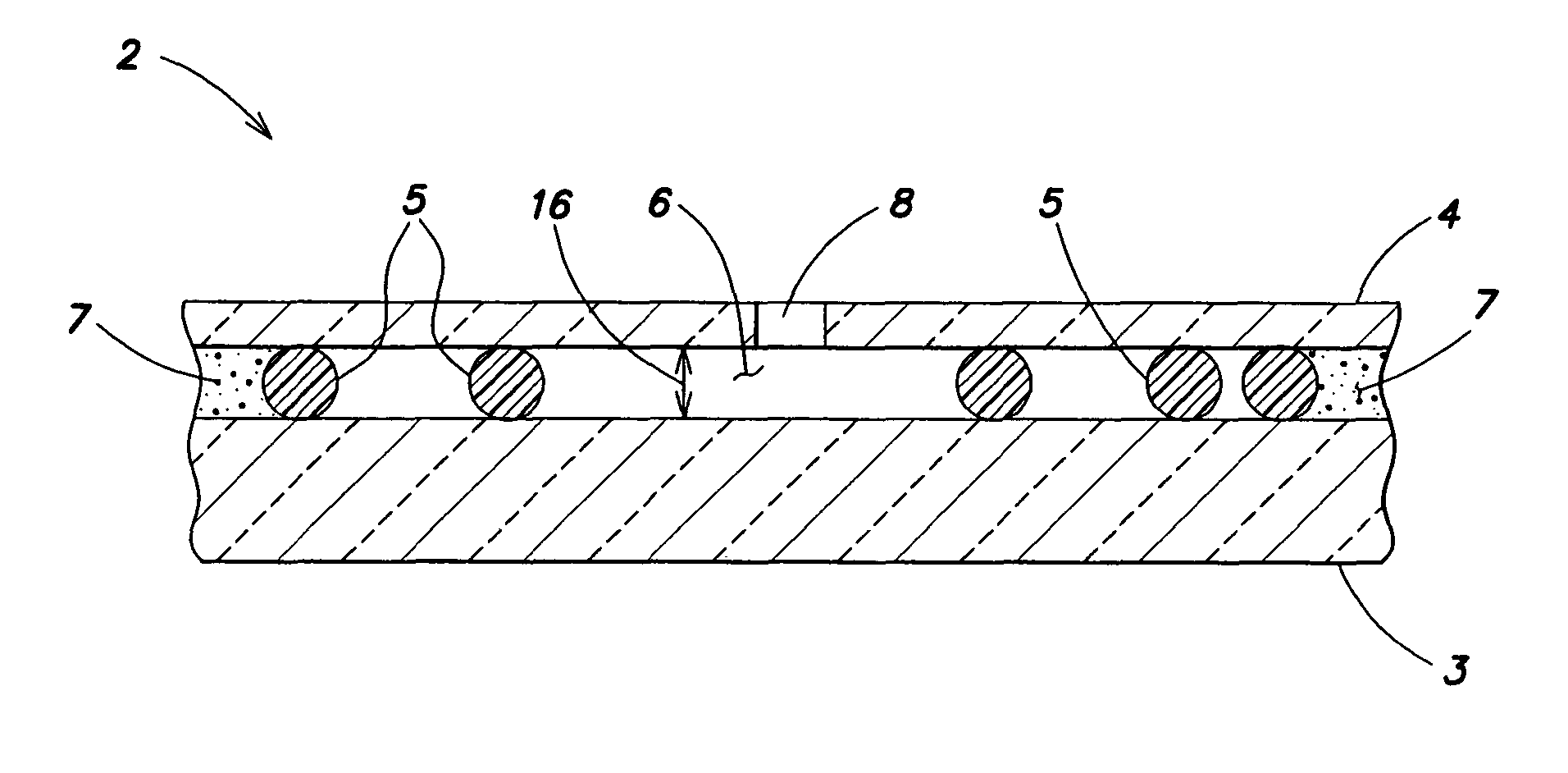
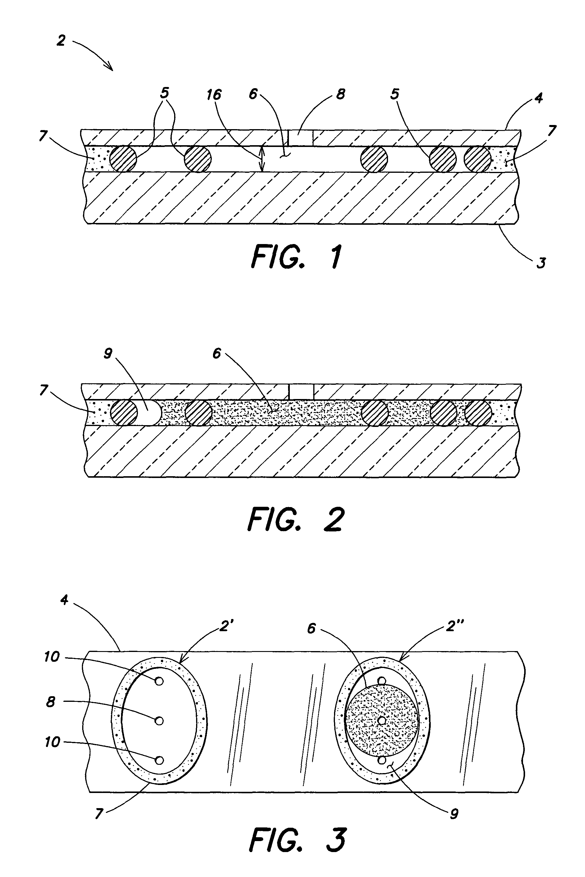
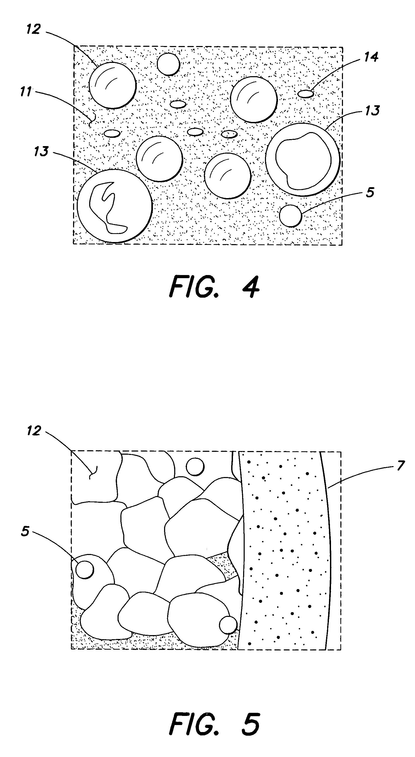
[0024]Referring to FIGS. 1-5, the present apparatus for analyzing biologic fluids includes one or more chambers 2 defined by a first planar member and a second planar member, separated from one another by a distance referred to hereinafter as the chamber height 16. At least one of the first planar member and the second planar member is sufficiently transparent so that a biologic fluid sample disposed within a chamber 2 may be imaged. To facilitate the description of the present invention, the planar members are referred to hereinafter as the “top” planar member 4 and the “bottom” planar member 3. The top planar member 4 hereinafter is also described as being transparent. In alternative embodiments, the bottom planar member 3 may be transparent rather than the top planar member 4, or in addition to the top planar member 4.

[0025]The planar members 3, 4 can be formed from a variety of materials, having different or identical properties. Patent Cooperation Treaty Patent Publication No. ...


PUM

PropertyMeasurementUnit
heightaaaaaaaaaa
chamber heightaaaaaaaaaa
heightaaaaaaaaaa

Abstract

A method and an apparatus for enumerating one or more specific elements within a biologic fluid sample are provided. An embodiment of the method includes the steps of: a) providing a chamber formed between a first planar member that is transparent and a second planar member, which members are separated from one another by a substantially uniform height; b) introducing the biologic fluid sample into the chamber, wherein the chamber height is sized such that the sample extends between the first and second members, and sized relative to the specific elements within the sample such that the specific elements non-uniformly distribute within the sample upon introduction into the chamber; c) examining substantially all of the sample within the chamber and enumerating all of at least one of the specific elements; d) determining the volume of sample contained within the chamber; and e) determining the number of the at least one of the specific elements per unit volume.

Description

[0001]Applicant hereby claims priority benefits under 35 U.S.C. §119(e) of U.S. Provisional Patent Application entitled APPARATUS AND METHOD FOR PERFORMING BLOOD CELL COUNTS, filed Oct. 19, 2005, Ser. No. 60 / 728,058, the disclosure of which is herein incorporated by reference.BACKGROUND OF THE INVENTION[0002]1. Technical Field[0003]The present invention relates to chambers for analyzing biologic fluids in general, and to chambers that permit the enumeration of particulate matter within the biologic fluid in particular.[0004]2. Background Information[0005]The complete blood count (CBC) is the most frequently performed set of tests for whole blood and includes a number of separate analyses such as the white blood count (WBC), the red blood cell count (RBC), and platelet count, among others. The methods used vary in completeness of analyte set, complexity and cost of equipment, and per-test cost. The least complex methods, such as the QBC® method described in U.S. Pat. No. 4,156,570, h...

Claims


Application Information

Patent Timeline
Patent Type & Authority Patents(United States)
IPC IPC(8): G01N33/00G01N31/00G01N15/06G01N33/48
CPCB01L3/508G01N15/1463B01L2200/0684B01L2300/0822Y10T436/101666G01N2015/008G01N2015/0084G01N2015/1486G01N2015/0073B01L3/5027G02B21/34
Inventor WARDLAW, STEPHEN C.
Owner WARDLAW PARTNERS
Why Eureka
Try Eureka