Ultrasonic transducer array and a method for making a transducer array

a transducer array and ultrasonic technology, applied in piezoelectric/electrostrictive transducers, mechanical vibration separation, generators/motors, etc., can solve the problems of limited parametric ability and maximum sound pressure level, limited overall performance, and difficult to achieve, so as to reduce the manufacturing tolerance of individual transducers, the effect of low manufacturing cost and high performan

Inactive Publication Date: 2010-06-08
SONY CORP
View PDF12 Cites 11 Cited by
  • Summary
  • Abstract
  • Description
  • Claims
  • Application Information

AI Technical Summary

Benefits of technology

[0014]Thus, since each vibrator is provided with electrical contact to the two plates, the plates may function as the respective terminals of the transducer array, without requiring an additional step, carried out individually for each transducer, of forming electrodes to contact the vibrators.
[0023]Note that the first of these steps may be performed as a single step, in which the vibrator elements are attached to the back plate substantially simultaneously. Thus, the fabrication process can more easily be carried out as a batch process. This has the advantages of making possible a low manufacturing cost and high performance, since the manufacturing tolerances of the individual transducers are reduced.

Problems solved by technology

This device is good for many applications, but its parametric ability and maximum sound pressure level are limited due to its size.
Firstly, it is difficult to align all the transducer elements. Ideally the central axis (line c-c′ in FIG. 2) in each element would be perfectly perpendicular to the support frame 21 and all the elements would be at the same level. However since there are non-uniform adhesion points 16 sandwiched between the transducer's ceramic plate 13 and the support frame 21 this is highly difficult to achieve in practice. As a result, each transducer element has a slightly different phase which limits the overall performance.
Secondly, the case 18 or even the ceramic plate 13 of each transducer occupies substantial space, making it more difficult to provide a thin and compact array aperture for mobile device applications. Furthermore, the case 18 tends to increase the centre-to-centre distance between adjacent transducer elements, which is not conducive to suppressing the side-lobes of the transmitted ultrasonic wave.
Thirdly, placing commercial transducers onto a support frame one by one to form an array, and electrically connecting them one by one, limit manufacturability and decrease both uniformity and repeatability.

Method used


Image

  • Ultrasonic transducer array and a method for making a transducer array
  • Ultrasonic transducer array and a method for making a transducer array
  • Ultrasonic transducer array and a method for making a transducer array

Examples


Embodiment Construction

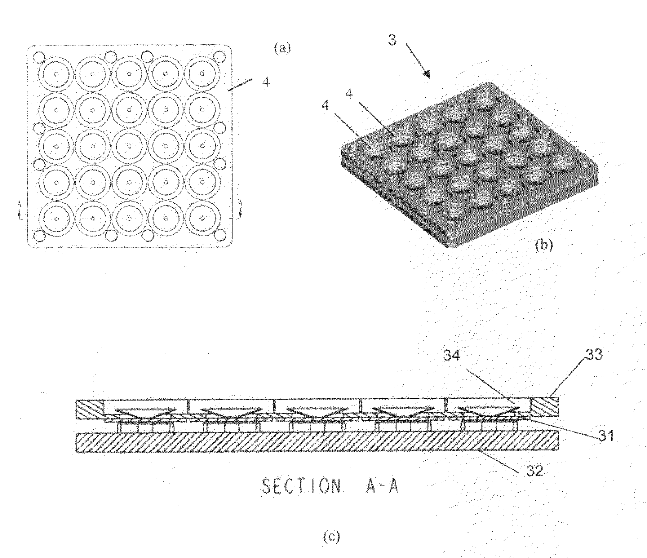
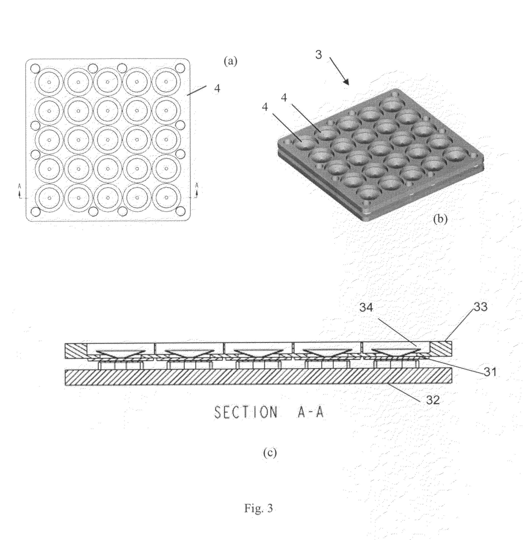
[0033]FIG. 3 shows a PZT ultrasonic transducer array 3 which is an embodiment of the present invention. It is shown in a plan view in FIG. 3(a) and in a perspective view in FIG. 3(b). FIG. 3(c) is a cross-sectional view, in the plane shown by the line A-A of FIG. 3(a). The array 3 comprises a 5×5 array of transducer elements 4 (in other embodiments other types of array are possible).

[0034]Each element 4 includes a two-layer vibrator unit 31, and a resonator 34 in the form of a lightweight cone. The structure of the vibrator unit 31 is shown in FIG. 4. The vibrator unit 31 includes one planar circular layer which is a metal membrane 311, and another planar circular layer which is a PZT wafer 312. The set of 25 resonators 34 (each of which is part of a respective one of the 25 transducers) can collectively be considered as a layer 41. Similarly, the set of 25 metal membranes 311 collectively form a non-contiguous layer 42, and the set of 25 PZT wafers 312 collectively form a non-conti...


PUM

PropertyMeasurementUnit
conductiveaaaaaaaaaa
ultrasonic frequencyaaaaaaaaaa
piezoelectricaaaaaaaaaa

Abstract

A transducer array comprises a conductive back plate 32, a conductive front plate 33 having openings 62, and a plurality of piezoelectric vibrator elements 31 located in an array between the plates. The vibrator elements 31 are two-layer elements which each include a metal portion 311 and a PZT element 312. These elements 311, 312 are in electrical contact with the respective plates. The vibrator elements 31 are attached to support elements 51 upstanding as part of the back plate 32. The transducer array can be formed as a batch process in which the vibrator elements 31 are formed simultaneously, and then simultaneously attached to the support elements 51.

Description

FIELD OF THE INVENTION[0001]The present invention relates to a transducer array suitable for generating sounds in an ultrasonic frequency range (an “Ultrasonic Transducer Array”), and to a method of making it. The transducer array includes transducer elements including piezoelectric material, such as PZT.BACKGROUND OF THE INVENTION[0002]It is well know in the art to use piezoelectric devices as ultrasonic transducers. For example ceramic-based piezoelectric lead zircomate titanate (PZT) is used in commercially available ultrasonic transducers. FIG. 1 illustrates a typical prior art PZT ultrasonic transducer, including a two-layer transducer element 10 with a poled PZT sheet 11 bonded with a metal sheet 12.[0003]The transducer element 10 is fixed by silicone adhesive 14 on a ceramic support 13 within a case 18. A pair of pins 15 are electrically connected to the PZT layer 11 and are fixed in place though the ceramic support 13 by an adhesive 16. The transducer element 10 is deflected...

Claims


Application Information

Patent Timeline
Patent Type & Authority Patents(United States)
IPC IPC(8): H01L41/09H04R17/00H04R31/00
CPCB06B1/0622Y10T29/42
Inventor GAO, PENGYEO, CHING BIINGSUN, XIAOBINGOKADA, KANZO
Owner SONY CORP
Why Eureka
Try Eureka