Thin display structure

a display structure and thin technology, applied in the field of thin display structures, can solve the problems of increasing transportation costs and inconvenience for users, and achieve the effects of increasing transportation costs, thin display structures, and increasing packaging spa

Active Publication Date: 2010-06-08
AMTRAN TECH CO LTD
View PDF9 Cites 24 Cited by
  • Summary
  • Abstract
  • Description
  • Claims
  • Application Information

AI Technical Summary

Benefits of technology

[0008]According to the above conventional art, the foot of the thin display increases the space of the package, and thereby increasing the transportation cost. If the thin display is hung on the wall surface, the foot must be detached, which is inconvenient to the user. Accordingly, the present invention is directed to providing a thin display structure with a rotatable foot.
[0010]In the thin display structure according to the present invention, the support unit is designed to be rotatably disposed. As for the manufacturers, when packing after finishing the manufacturing process, the support unit can be hidden in the bottom of the case, and from the perspective of the external appearance, the support unit does not protrude from the thin display. Besides selecting some necessary buffer material, the packing case can be designed to be approximate to the volume of the thin display, so as to increase the amount loaded in the freight space, thereby enhancing the transportation efficiency, reducing the package cost and the transportation cost. Furthermore, the rotation of the support unit can be achieved simply through manual operation, without requiring any other tools. When the user intends to hang the thin display on the wall surface, it can be achieved by directly rotating the support unit without detaching the support unit, which thus is very convenient in operation.

Problems solved by technology

According to the above conventional art, the foot of the thin display increases the space of the package, and thereby increasing the transportation cost.
If the thin display is hung on the wall surface, the foot must be detached, which is inconvenient to the user.

Method used


Image

  • Thin display structure
  • Thin display structure
  • Thin display structure

Examples


Embodiment Construction

[0029]According to the thin display structure disclosed in the present invention, the thin display refers to a display, such as an LCD TV and a PDP TV, and the present invention is optimally applied to large-size thin displays.

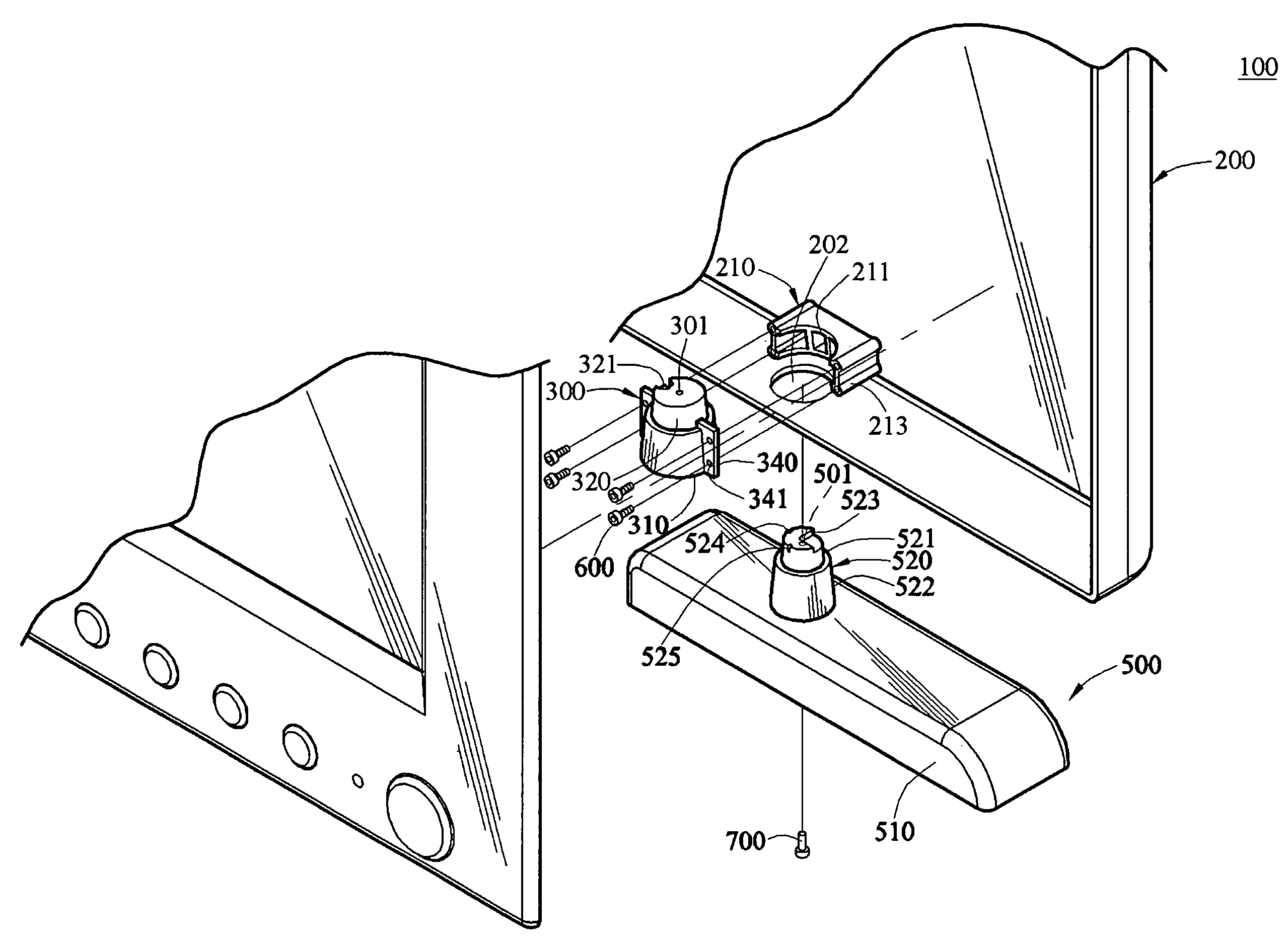
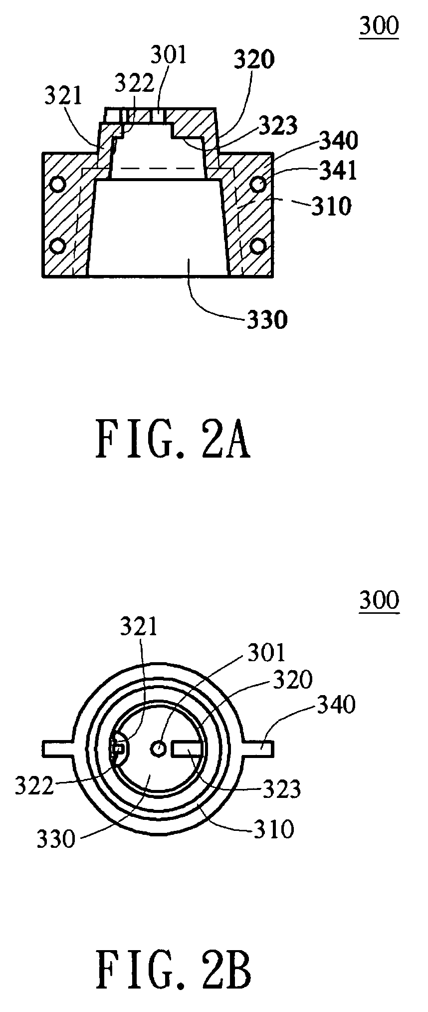
[0030]Referring to FIG. 1, together with FIGS. 2A, 2B, 3, and 6, the thin display structure of the first embodiment of the present invention includes a case 200, a joining sleeve 300, and a support unit 500. The case 200 is used to cover a display panel (not shown) that is provided for the user to view the images, and thus the case 200 covers and protects the display panel. Furthermore, the case 200 has a through hole 202 at the bottom corresponding to the joining sleeve 300, for the support unit 500 to pass through. A retaining bracket 210 is disposed on the case 200 at the bottom part close to the wall surface and corresponding to the through hole 202. The retaining bracket 210 further includes a joint portion 211 and a plurality of positioning posts 213 loc...


PUM


Abstract

A thin display structure including a case, at least two joining sleeves disposed at the bottom of the case, and at least two support units with the transverse width similar to the thickness of the case is provided. The support units are rotatably disposed in the joining sleeves, such that the support units can rotate with respect to the case, so as to have a receiving position hiding in the case and a supporting position protruding from the case. In the receiving position, the thin display can be received in a packing case or hung on a wall surface, and in the supporting position, the thin display can stand on a plane.

Description

BACKGROUND OF THE INVENTION[0001]1. Field of Invention[0002]The present invention relates to a display structure. More particularly, the present invention relates to a thin display structure with a rotatable support unit.[0003]2. Related Art[0004]Compared with a conventional cathode ray tube display (CRT DISPLAY), a thin display, such as a liquid crystal display television (LCD TV) or a plasma display panel television (PDP TV), not only has advantages of being light in weight, and compact in size, and occupying a relative small space, but also has various functions of externally connecting to a computer, and audio-visual home appliances, and thus the thin display has generally become a standard device for the current digital family.[0005]The thin display generally has a foot for supporting the thin display to be placed on a TV cabinet, and the area of the foot is generally larger than the thickness of the thin display, so as to stably support the thin display to stand on the TV cabi...

Claims


Application Information

Patent Timeline
Patent Type & Authority Patents(United States)
IPC IPC(8): G06F1/16
CPCF16M11/00F16M11/08H05K5/02F16M13/02F16M2200/08
Inventor HSU, HUI-HSIUNG
Owner AMTRAN TECH CO LTD
Why Eureka
Try Eureka