Electromechanical valve actuator assembly

a technology of electromechanical valve actuators and actuator assemblies, which is applied in the direction of non-mechanical valves, valve arrangements, machines/engines, etc., can solve the problems of limiting the ease of engine serviceability, limiting the space available, and limiting the placement of all linear electromechanical valve actuators over a particular cylinder, so as to increase the ease of serviceability and eliminate potential interference

Inactive Publication Date: 2005-06-02
VISTEON GLOBAL TECH INC
View PDF22 Cites 3 Cited by
  • Summary
  • Abstract
  • Description
  • Claims
  • Application Information

AI Technical Summary

Benefits of technology

[0008] Careful arrangement of electromechanical valve actuators to create a compact assembly increases ease of serviceability, provides space for access to various engine components such as the spark plug, provides additional package space for wiring harnesses and control modules of electromechanical valve actuators, and eliminates potential interference between the actuators and components in the vehicle engine compartment or the vehicle body.

Problems solved by technology

One problem with linear electromechanical valve actuators is that each linear electromechanical valve actuator operationally coupled to the associated valve includes a relatively large set of electromagnets for opening and closing the valves (FIG. 1).
The size of the electromagnets makes it difficult to position all of the linear electromechanical valve actuators over a particular cylinder, especially for engines that have four or more valves per cylinder.
The size of linear electromechanical valve actuators may also limit the ease of serviceability of the engine, such as restricting the space available for changing the spark plug.
Another problem with linear electromechanical valve actuators is that linear electromechanical valve actuators generally have a substantial height extending from the cylinder head of an engine.
The height of the linear electromechanical valve actuators creates difficulty in packaging the linear actuators on engines in today's compact engines and in today's full engine compartments.
For example, linear electromechanical valve actuators may interfere with other engine parts, other components or accessories located in the engine compartment, and even the vehicle body, such as, the hood.
Yet another problem with linear electromechanical valve actuators is that they generally draw a substantial amount of power from the vehicle's electrical system, as compared with lever electromechanical valve actuators, thereby putting additional demand on the alternator in today's power hungry vehicles.
However, a major problem with lever electromechanical valve actuators is still the package size required on the cylinder head.
Due to the set locations of valves and spark plugs by engine designers, designs for lever electromechanical valve actuator assemblies on the engine have been traditionally limited.
The difficulty in changing the spark plug as well as servicing the actuators is compounded in that at least two of the actuators are completely within the perimeter of the cylinder walls extended toward the actuators.

Method used


Image

  • Electromechanical valve actuator assembly
  • Electromechanical valve actuator assembly
  • Electromechanical valve actuator assembly

Examples


Embodiment Construction

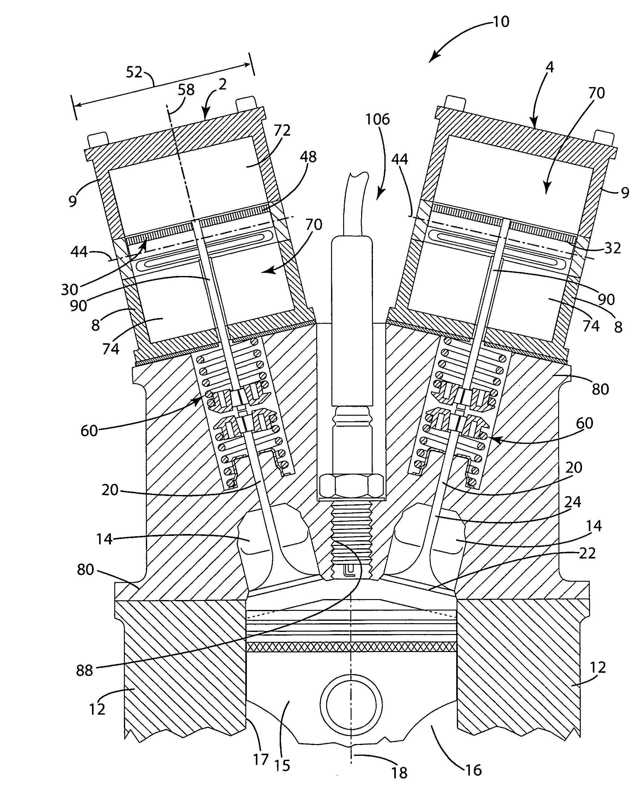
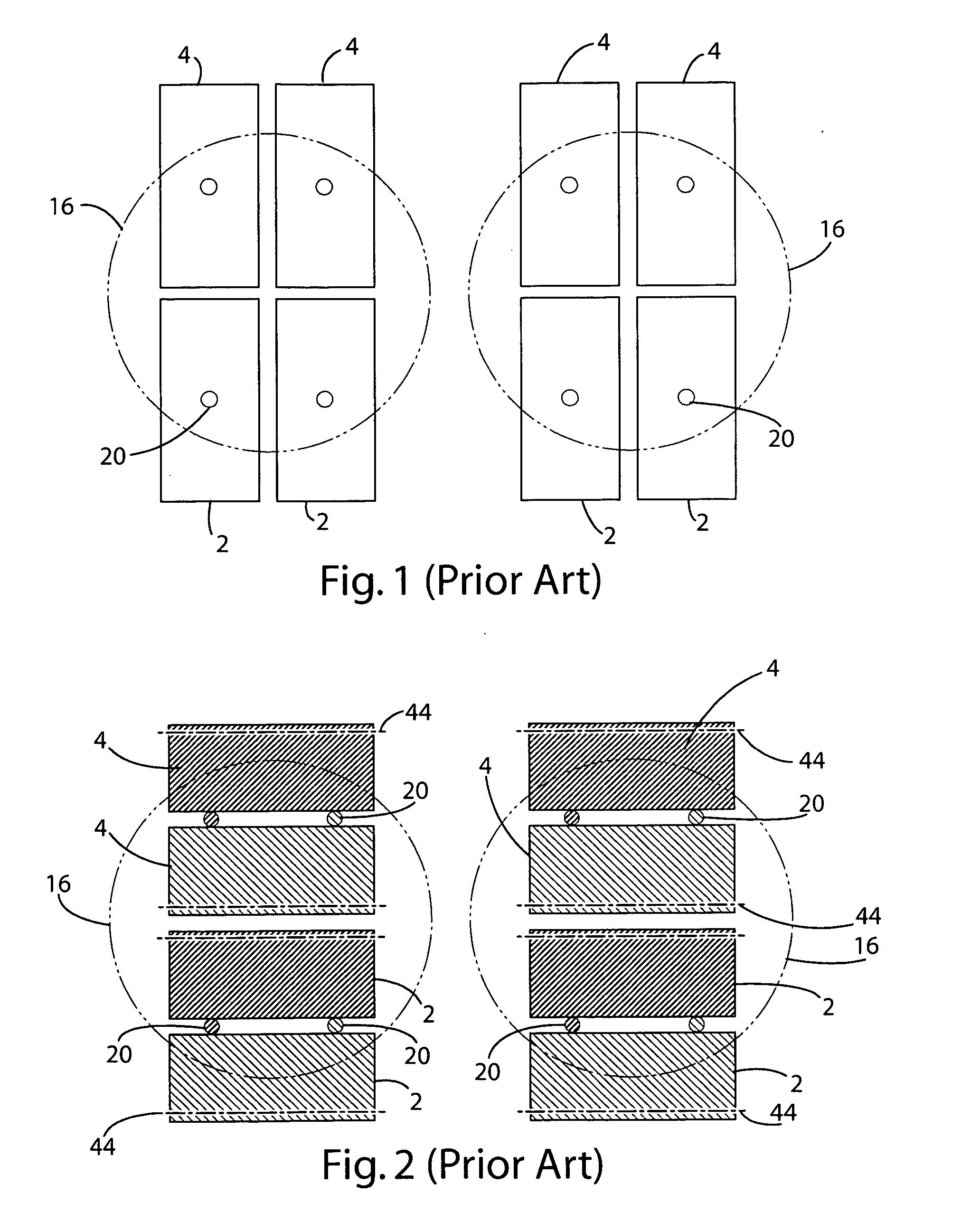
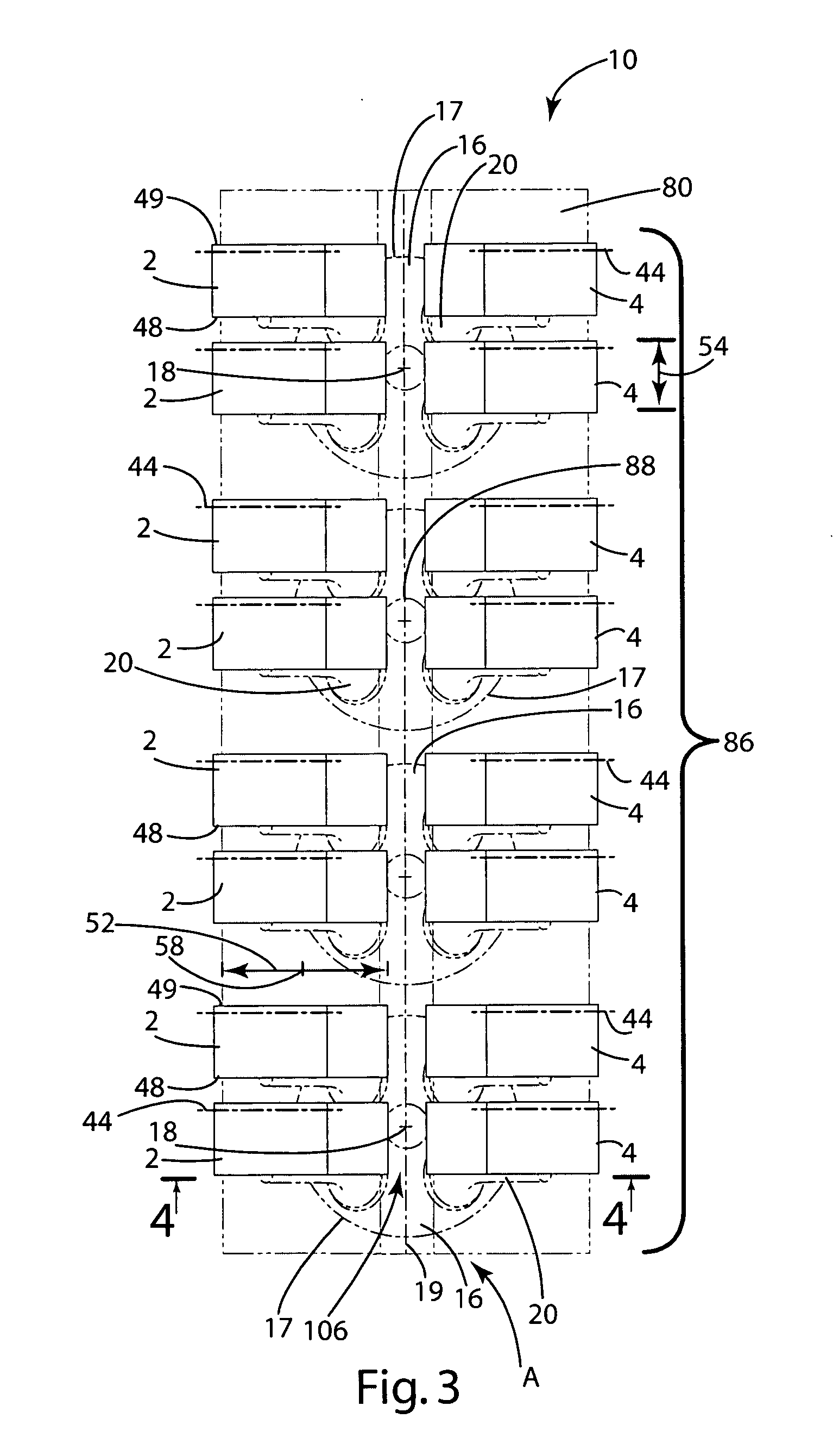
[0029] A lever electromechanical valve actuator assembly shown generally at 10 in FIG. 3 is mounted on a cylinder head 80 of an internal combustion engine 12 and with individual actuators 2, 4 being at least partially located over an associated cylinder 16. The actuators 2, 4 operably associated with a particular cylinder 16 may be referred to as actuator groups 11. Each actuator 2, 4 of the lever electromechanical valve actuator assembly 10 is connected to a valve 20, such as an intake or exhaust valve, to open and close the valve 20 as desired. The electromechanical valve actuator assembly 10, as illustrated in FIG. 3, and as illustrated in the alternative embodiments shown in FIGS. 5-15, provides a more compact arrangement while allowing greater serviceability and easier assembly.

[0030] The electromechanical valve actuator assembly 10 generally includes both intake actuators 2 and exhaust actuators 4 as illustrated in FIGS. 3 and 4-13. Of course, the actuator assembly 10 may inc...


PUM


Abstract

A lever electromechanical valve actuator assembly and arrangement of electromechanical valve actuators that creates a compact actuator assembly to increase ease of serviceability, provide space for engine components and eliminate interference between the actuators and components in the vehicle engine compartment.

Description

CROSS-REFERENCE TO RELATED APPLICATION [0001] This application is a continuation-in-part of U.S. patent application Ser. No. 10 / 963,892, filed Oct. 13, 2004 which claims the benefit of U.S. Provisional Application No. 60 / 510,988, filed Oct. 14, 2003, the entire disclosure of each application is considered part of the disclosure of this application and is hereby incorporated by reference.BACKGROUND OF THE INVENTION [0002] The present invention relates to electromechanical valves actuators and, more particularly, to compact electromechanical valve actuator assemblies and the arrangement of electromechanical valve actuators on an engine. [0003] As engine technology advances and manufacturers strive to increase engine power, improve fuel economy, decrease emissions, and provide more control over engines, manufacturers are developing electromechanical valve actuators (also known as electromagnetic valve actuators or EMVA) to replace cam shafts for opening and closing engine valves. Elect...

Claims


Application Information

Patent Timeline
Patent Type & Authority Applications(United States)
IPC IPC(8): F01L9/20
CPCF01L9/04F01L2009/0405F01L2009/0434F01L2009/0409F01L2009/0407F01L2009/2107F01L2009/2105F01L2009/2109F01L2009/2134F01L9/20
Inventor CHUNG, HA T.HOPPER, MARK L.NORTON, JOHN D.SWALES, SHAWN H.
Owner VISTEON GLOBAL TECH INC
Why Eureka
Try Eureka