Multimode interference device with side input/output ports

a multi-mode interference and side input/output technology, applied in the field of integrated optic communication, can solve the problems of unwanted signal loss, unwanted non-uniformity in the power at the final output, and three weaknesses of the conventional design

Inactive Publication Date: 2010-06-08
US SEC THE ARMY THE
View PDF10 Cites 19 Cited by
  • Summary
  • Abstract
  • Description
  • Claims
  • Application Information

AI Technical Summary

Benefits of technology

[0022]Additionally, the plurality of ports may be positioned at an acute angle with respect to the longitudinal axis of the multimode interference region. The method may further comprise connecting a phase-changing device to one of the at least one input port and the at least one output port. Also, each of the plurality of ports may be linearly configured. The method may further comprise connecting the at least one input port to the at least one output port. Furthermore, the method may comprise offsetting the plurality of ports relative to one another. Alternatively, the method may further comprise offsetting the plurality of ports relative to an end portion of the multimode interference region, wherein the end portion of the multimode interference region is substantially transverse to the longitudinal axis of the multimode interference region. The multimode interference region may comprise at least one subregion having an effective refractive index running longitudinally within the multimode interference region. Moreover, the method may further comprise configuring the at least one subregion with a slot.

Problems solved by technology

Also, laterally separating the guides requires bends, which cause unwanted signal loss, both from mode mismatch at guide boundaries and from radiative effects of curvature.
For 1×N power splitters, the bends in the guides that are necessary to separate the intermediate outputs often cause unwanted nonuniformity in the powers at the final outputs.
Unfortunately, there tends to be three weaknesses to this conventional design.
Making the slot too wide, so that it overlaps with the input / output ports, lessens the throughput and increases the crosstalk, both of which are undesirable.
The length must be set to a compromise length, which compromises the overall performance of the switch 41.
For end-porting, angled input / output guides degrade the performance unless the MMI region is non-rectangular (e.g., bow-tie shaped), which introduces additional difficulties in design and fabrication.

Method used


Image

  • Multimode interference device with side input/output ports
  • Multimode interference device with side input/output ports
  • Multimode interference device with side input/output ports

Examples


Embodiment Construction

[0046]The embodiments of the invention and the various features and advantageous details thereof are explained more fully with reference to the non-limiting embodiments that are illustrated in the accompanying drawings and detailed in the following description. It should be noted that the features illustrated in the drawings are not necessarily drawn to scale. Descriptions of well-known components and processing techniques are omitted so as to not unnecessarily obscure the embodiments of the invention. The examples used herein are intended merely to facilitate an understanding of ways in which the embodiments of the invention may be practiced and to further enable those of skill in the art to practice the embodiments of the invention. Accordingly, the examples should not be construed as limiting the scope of the embodiments of the invention.

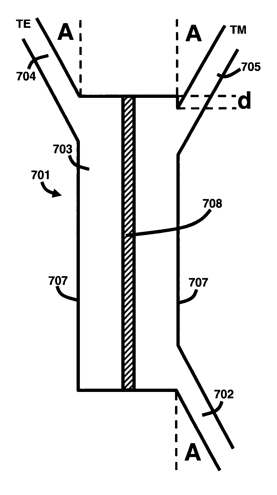
[0047]As mentioned, there remains a need to improve the performance of the conventional MMI devices by increasing the lateral separation of the ...


PUM


Abstract

A multimode interference device and a method of configuring the same comprises a multimode interference region having a major axis; and a plurality of ports connected to a side portion of the multimode interference region, wherein the side portion is positioned in a direction other than perpendicular to the major axis.

Description

GOVERNMENT INTEREST[0001]The embodiments of the invention described herein may be manufactured, used, and / or licensed by or for the United States Government.BACKGROUND OF THE INVENTION[0002]1. Field of the Invention[0003]The embodiments of the invention generally relate to integrated-optic communications, and more particularly to a multimode interference device for use in telecommunications, sensing, and related applications.[0004]2. Description of the Related Art[0005]Multimode interference (MMI) devices are useful for power splitting and for the separation / combination of wavelengths or polarizations (SCWP), usually in integrated-optic (IO) systems. A typical MMI device consists of a MMI region separated by an input port and an output port. The ports are where input / output guides connect to the MMI region. Typically, in conventional MMI devices, the input and output guides only connect to the ends of the MMI region; i.e., they are end-ported.[0006]Power splitting devices are requir...

Claims


Application Information

Patent Timeline
Patent Type & Authority Patents(United States)
IPC IPC(8): G02B6/12G02B6/26
CPCG02B6/12007G02B6/126G02B6/29344G02B2006/12154G02B2006/12138
Inventor MACKIE, DAVID M.
Owner US SEC THE ARMY THE
Why Eureka
Try Eureka