Information error recovery apparatus and methods

a technology of information error and recovery apparatus, applied in error detection/correction, instruments, computing, etc., can solve problems such as errors, single- or multi-bit errors affecting l2 cache memory contents, and cache memory data or instruction contents can also be corrupted, so as to reduce downtime and maintenance resources

Inactive Publication Date: 2010-06-08
WSOU INVESTMENTS LLC
View PDF9 Cites 4 Cited by
  • Summary
  • Abstract
  • Description
  • Claims
  • Application Information

AI Technical Summary

Benefits of technology

[0010]Some embodiments of the invention provide a low-impact centralized means of recovering, in software and in real-time, from CPU to L2 cache errors that might occur due to a number of different factors, so as to reduce downtime and maintenance resources in systems that employ such processor / cache architectures.
[0023]A method is also provided, and includes monitoring information, which is retrieved from an information store for use by a processor in a software execution flow, to detect errors, and, responsive to detection of an error in the retrieved information, suspending the software execution flow of the processor, disabling use of the information store by the processor, and allowing the software execution flow of the processor to resume using information from a further information store in which the retrieved information is also stored.

Problems solved by technology

Single- or multi-bit errors that affect L2 cache memory contents may arise in any of various scenarios.
Errors may occur, for example, during transfer of data or instructions (writes) from a Central Processing Unit (CPU) main memory to the cache, during transfer of data or instructions (reads) from the cache to the CPU, or during modification of data in the cache as instructions are executed.
Cache memory data or instruction contents can also be corrupted due to soft errors, firm errors, and / or hard errors while information is stored in an external memory device.
The causes of data or instruction corruption in CPU to L2 cache memory systems may include, for example, any or all of marginal timing variations occurring naturally in a design due to component and / or manufacturing differences that affect operational characteristics of components, memory or other component manufacturing defects that cause intermittent “glitches” in a system under a specific set of conditions, and soft-errors due to external phenomena such as cosmic rays.
SSRAM devices, which are often used to implement cache memories, tend to be susceptible to a number of factors such as temperature, humidity, equipment slot for electronic card-based implementations, noise, etc.
Even if ECC protection were provided for an L2 cache, the issue of error handling would not be completely solved since ECC schemes have limited error correction capabilities.
Therefore, in external L2 cache applications, single- and most multi-bit errors in the L2 cache memory are detected on the CPU as parity errors.
However, if the error / corruption does not affect data that has been modified only in the cache (i.e., data that has not been synchronized between the cache and the main memory), this simple response is exaggerated and may cause a long and unnecessary interruption in services inherent in the CPU.
Traditional approaches for responding to or correcting L2 cache errors include detecting an error in software and triggering a system crash, which requires a complete reset to recover from the detected error and can result in a significant disruption in a software application or the operation of a communication network, for example.
Hardware-based ECC approaches that use ECC for detecting and correcting single-bit errors can mitigate the impact of errors or corruption, but do not eliminate the problem in that multi-bit errors can be detected but not corrected.
ECC-based error checking also tends to be slow.

Method used


Image

  • Information error recovery apparatus and methods
  • Information error recovery apparatus and methods
  • Information error recovery apparatus and methods

Examples


Embodiment Construction

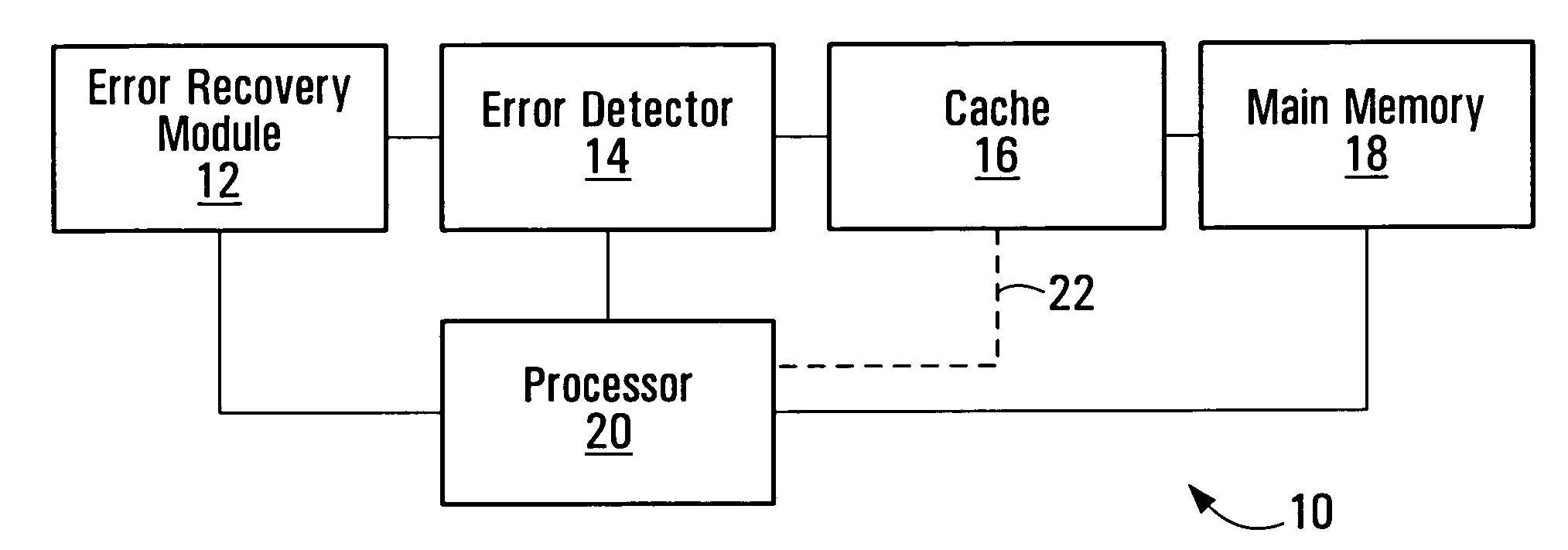
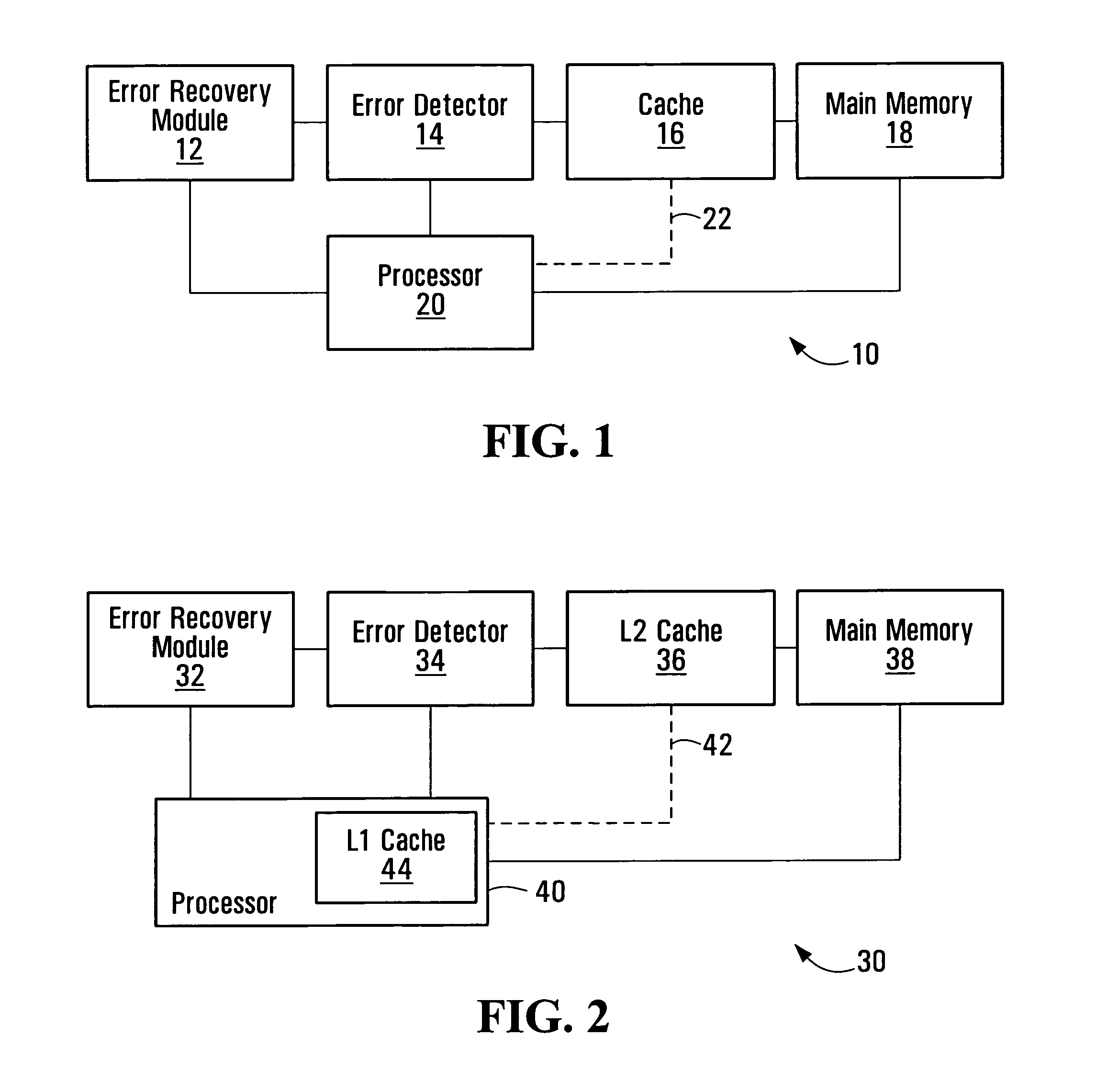
[0037]FIG. 1 is a block diagram of an electronic device in which embodiments of the invention may be implemented. The electronic device 10 includes a processor 20, an error recovery module 12 operatively coupled to the processor 20, an error detector 14 operatively coupled to the error recovery module 12 and to the processor 14, a cache 16 operatively coupled to the error detector 14, and a main memory 18 operatively coupled to the cache 16 and to the processor 20.

[0038]The processor 20 may be operatively coupled to the cache 16 directly, as shown at 22, or indirectly, through the error detector 14. The two types of interconnections represent different access and error detection schemes, as described in further detail below.

[0039]The device 10 represents one possible implementation of an embodiment of the invention. Other embodiments having fewer, further, or different components with similar or different interconnections are also contemplated. The invention is in no way limited to ...


PUM


Abstract

Information error recovery apparatus and methods are disclosed. Responsive to an error detected in information retrieved from an information store for use by a processor in a software execution flow, the software execution flow of the processor is suspended. Use of the information store by the processor is also disabled. The software execution flow of the processor is allowed to resume using information from a further information store in which the retrieved information is also stored. This allows recovery from errors without resetting the processor. The information store may be reloaded from the further information store and re-enabled for use by the processor. The information store and the further information store are a cache and a main memory, respectively, in one embodiment.

Description

FIELD OF THE INVENTION[0001]This invention relates generally to information processing and, in particular, to recovering from errors.BACKGROUND[0002]An information store such as a cache can be used to reduce the time that it takes a processor to access memory for instructions and data. A cache is a smaller but faster memory that stores copies of information from the most frequently used main memory locations. Nearly all microprocessor systems employ cache memories for this performance benefit. Typically, cache memories consist of a Level 1 (L1)cache, which is relatively small and internal to the processor itself, and a larger Level 2 (L2)cache, which is implemented using external Synchronous Static Random Access Memory (SSRAM) devices that are not Error Correction Coding (ECC) protected.[0003]Single- or multi-bit errors that affect L2 cache memory contents may arise in any of various scenarios. Errors may occur, for example, during transfer of data or instructions (writes) from a Ce...

Claims


Application Information

Patent Timeline
Patent Type & Authority Patents(United States)
IPC IPC(8): G06F11/00
CPCG06F11/1064
Inventor KOKTAN, TOBY JAMESFRIESEN, LARRY
Owner WSOU INVESTMENTS LLC
Why Eureka
Try Eureka