Versatile caliper mounting and measurement accessory

a technology of calipers and accessories, applied in the field of calipers, can solve the problems of not being suitable for many applications, and the conventional sliding calipers are generally not suitable as generic machine positioning devices

Active Publication Date: 2010-06-15
MAG DRO
View PDF17 Cites 24 Cited by
  • Summary
  • Abstract
  • Description
  • Claims
  • Application Information

AI Technical Summary

Benefits of technology

[0005]A simple and inexpensive accessory for a standard caliper is provided to transform a standard caliper from a parts precision measuring tool into a generic machine positioning device.
[0007]The magnetic caliper mounting device mounts, via force of magnetic attraction alone, onto a flat metal surface, such as table saw top, a metal lathe carriage, or a milling machine table, and enables a conventional caliper to be used to precisely position wood-working, plastic-working, and metal-working pieces, such as the fence of a table saw fence, the table and spindle of a milling machine, and the carriage, top slide, and tailstock of a metal lathe. The magnetic caliper mounting device, when mounted on a vertical metal surface, also adapts a conventional caliper into a precise height gage.
[0008]The materials and tooling needed to manufacture the magnetic caliper mounting device are relatively inexpensive, and the magnetic caliper mounting device can be inexpensively incorporated into a kit that includes a conventional caliper.
[0010]Another version of the caliper mounting device includes two orthogonally-oriented scale-bar mounting channels for facilitating measurements, using two conventional calipers, in two dimensions. Yet other versions include one or more pivotable caliper holders to orient a caliper at a desired angle around the caliper holder's axis of rotation. Yet further versions include a universal joint operable to position the caliper at any angle with respect to the planar metal surface to which the device is mounted. Some versions include a permanent disc magnet, and other, more elegant versions of the caliper mounting devices include one or more switchable magnets to facilitate removal.

Problems solved by technology

Conventional handheld sliding calipers are relatively inexpensive, but they are not suitable for many applications, such as the positioning of a sawtable fence, a milling machine travel table or spindle, or a metal lathe carriage, top slide, or tailstock.
Stated another way, conventional handheld sliding calipers are generally not suitable as a generic machine positioning device.

Method used


Image

  • Versatile caliper mounting and measurement accessory
  • Versatile caliper mounting and measurement accessory
  • Versatile caliper mounting and measurement accessory

Examples


Embodiment Construction

[0067]In describing preferred and alternate embodiments of the technology described herein, as illustrated in FIGS. 1A-39B, specific terminology is employed for the sake of clarity. The technology described herein, however, is not intended to be limited to the specific terminology so selected, and it is to be understood that each specific element includes all technical equivalents that operate in a similar manner to accomplish similar functions.

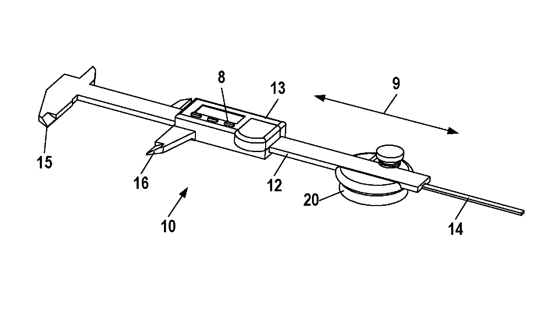
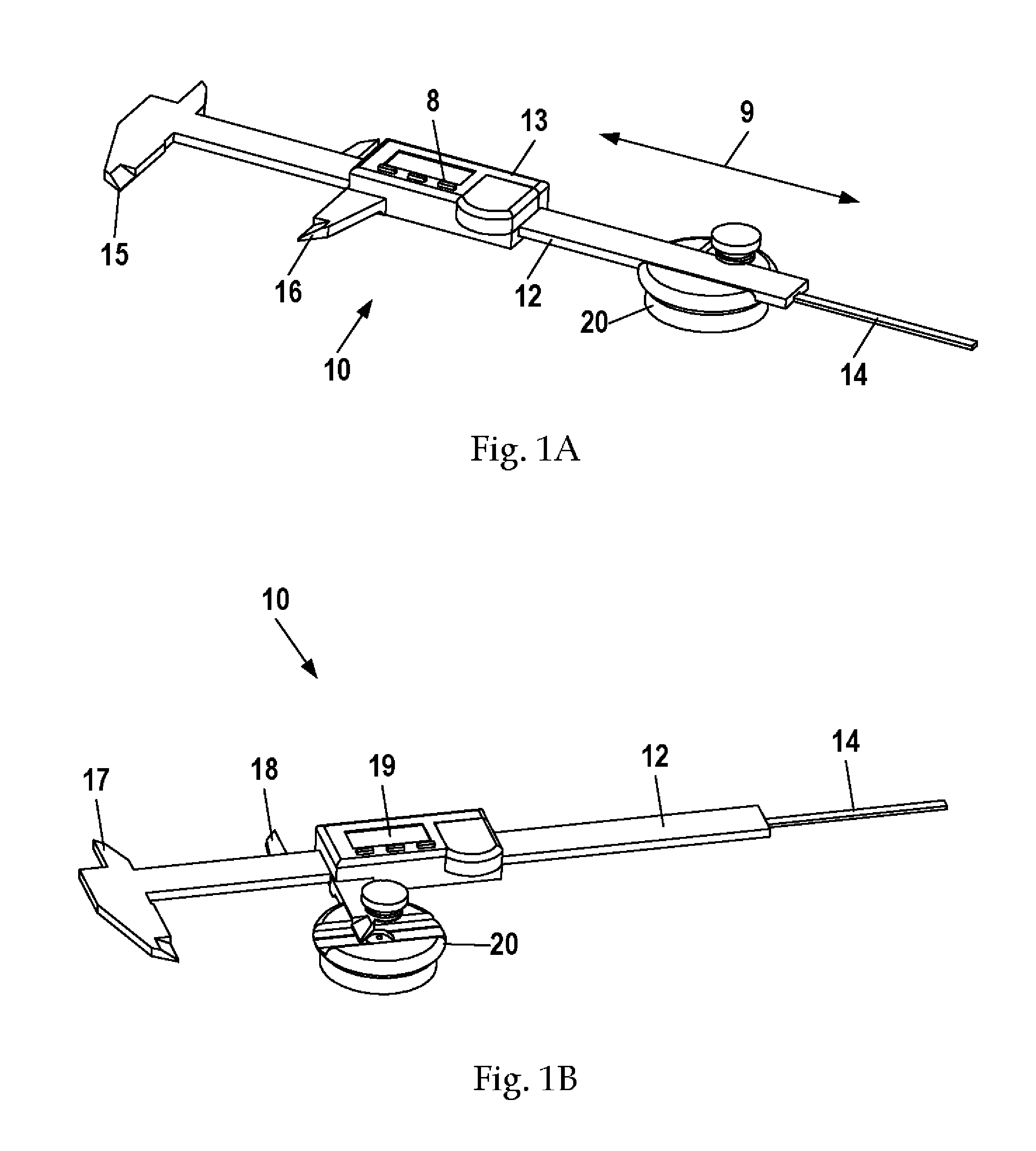
[0068]FIGS. 1A and 1B display a conventional sliding caliper 10 mounted in one embodiment of a magnetic caliper mounting apparatus 20. The caliper 10 comprises a scale bar 12, a movable frame 13, depth probe 14, a fixed outside jaw 15, a movable outside jaw 16, a fixed inside jaw 17, and a movable inside jaw 18. Movable outside jaw 16 and movable inside jaw 18 are rigidly connected to the movable frame 13. Depth probe 14 is also coupled to and moves synchronously with the movable frame 13. The particular caliper 10 depicted in the drawings al...


PUM


Abstract

Several caliper accessories are provided that make a conventional caliper suitable for more sophisticated applications traditionally reserved for more expensive measurement devices. One of these accessories, a magnetic caliper mounting device, has a shallow scale-bar-mounting channel for receiving the scale bar of the caliper, a retainer adapted to releasably secure the scale bar of the caliper within the channel of the caliper mount, and a magnet associated with the caliper mount to secure the apparatus to a planar metal surface. Another accessory, a caliper jaw extender, is either incorporated into a magnetic caliper mounting device or provided as a spring pack accessory to a magnetic caliper mounting device. The caliper jaw extender has a spring-biased retractor that hooks onto a caliper's movable frame and biases the frame toward an extended position. Kits are also provided comprising various combinations of a conventional caliper and accessories.

Description

FIELD OF THE INVENTION[0001]This invention relates generally to calipers, and more specifically, to mounting devices for calipers.BACKGROUND OF THE INVENTION[0002]Sliding calipers are handheld tools used to very precisely measure the distance between two symmetrically opposing sides. They are frequently used in checking or inspecting dimensions of parts and / or assemblies in metal, plastic, and woodworking fields. Conventional handheld sliding calipers are relatively inexpensive, but they are not suitable for many applications, such as the positioning of a sawtable fence, a milling machine travel table or spindle, or a metal lathe carriage, top slide, or tailstock. Stated another way, conventional handheld sliding calipers are generally not suitable as a generic machine positioning device.[0003]Typically, precise movements of machining tools such as sawtable fences, milling machine tables, and metal lathe carriages are made by recording the relative positions noted by crude markings ...

Claims


Application Information

Patent Timeline
Patent Type & Authority Patents(United States)
IPC IPC(8): G01B5/02
CPCG01B3/20
Inventor MOON, CHARLES W.
Owner MAG DRO
Why Eureka
Try Eureka