Masonry cavity wall construction and method of making same

a cavity wall and masonry technology, applied in the field of masonry walls, can solve the problems of detriment to the masonry trade, time-consuming process of reinforcing, labor-intensive, etc., and achieve the effect of facilitating the placement of rebar reinforcement, reducing labor intensity, and high thermal mass qualities of the wall structur

Inactive Publication Date: 2010-06-15
MASSIE MICHAEL C
View PDF13 Cites 48 Cited by
  • Summary
  • Abstract
  • Description
  • Claims
  • Application Information

AI Technical Summary

Benefits of technology

[0008]Another object and advantage of the present invention is the provision of a cavity wall structure of the class described which provides a masonry cavity wall having high thermal mass qualities of the wall structure by including the cast-in-place concrete structural wall component inwardly of the insulation layer of the wall.
[0009]Another object and advantage of the present invention is the provision of a masonry cavity wall structure of the class described which provides a secure and permanent interconnection of the interior wythe, exterior wythe, insulation and intermediate structural wall components of the finished wall construction.
[0010]Another object and advantage of the present invention is the provision of a masonry cavity wall construction of the class described which is arranged for on-site construction by a single masonry trade, thereby benefitting the masonry industry.
[0011]A still further object and advantage of the present invention is the provision of a masonry cavity wall structure of the class described in which the space provided between the inner wythe and the insulation panels is open during construction for facilitated placement of rebar reinforcement as may be desired or dictated preliminary to the introduction of fluid concrete therein during construction.
[0012]A still further object and advantage of the present invention is the provision of a masonry cavity wall which, by utilizing a reinforced, cast-in-place concrete load-bearing structural wall component, avoids the heretofore necessary provision of complex rebar reinforcing of the inner wythe component of the wall normally required when the inner wythe is the load-bearing component of the building wall.
[0013]A yet further object and advantage of this invention is the provision of a masonry cavity wall construction which simplifies building wall construction, time and labor.

Problems solved by technology

In this regard, and as is well understood by those skilled in the masonry industry, these heightened rebar reinforcing requirements now frequently result in a very labor-intensive, time-consuming process of reinforcing the concrete blocks with rebar arrangements that ever-increasingly occupy the space provided by aligned openings through the blocks in vertically-adjacent courses of individual concrete blocks forming the interior wythe wall.
The consequent expenses involved in the increased labor and time are unfortunately compelling the building industry to seek alternative wall constructions, to the detriment of the masonry trade and also at the sacrifice of aesthetic values.

Method used


Image

  • Masonry cavity wall construction and method of making same
  • Masonry cavity wall construction and method of making same
  • Masonry cavity wall construction and method of making same

Examples


Embodiment Construction

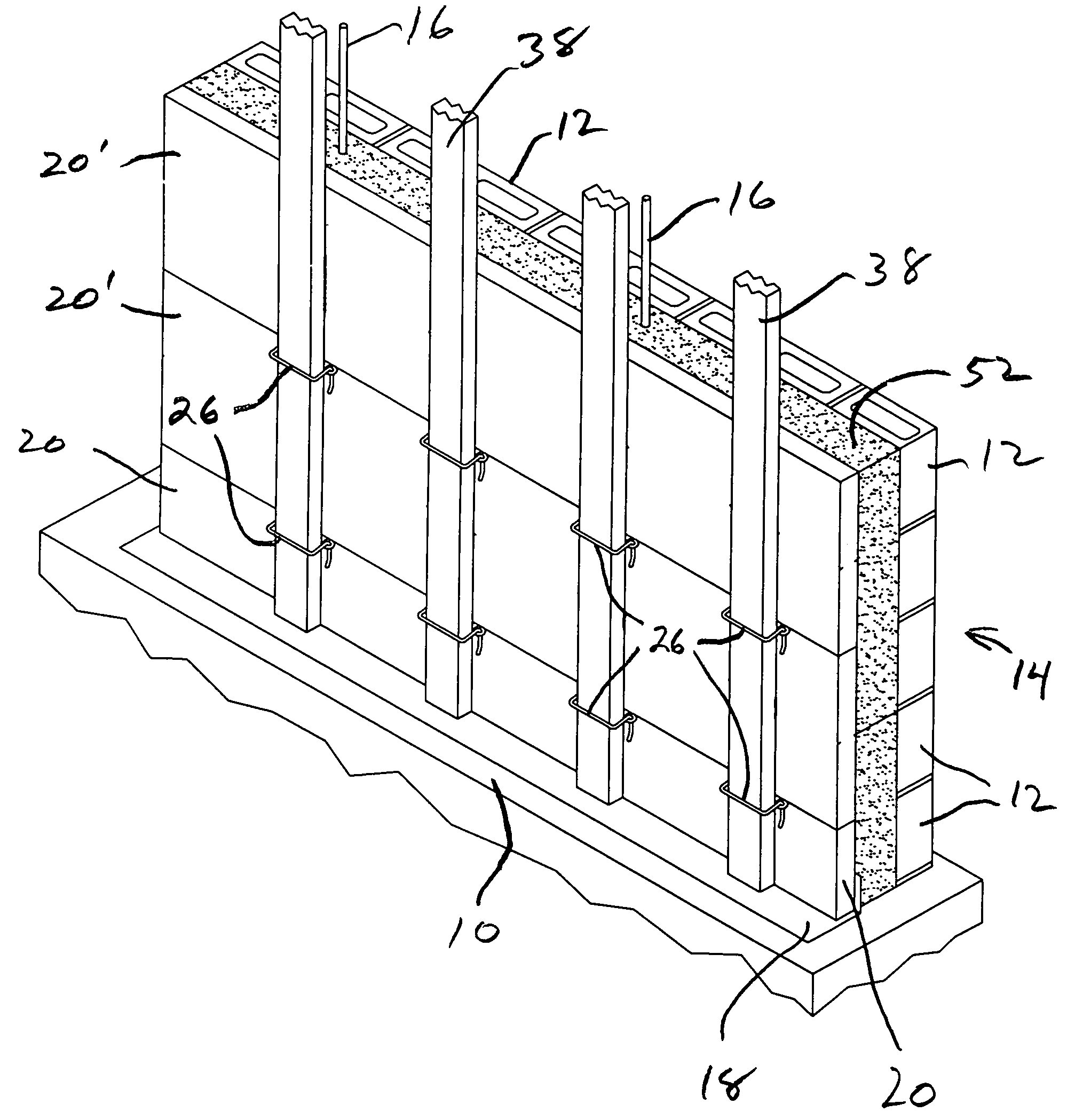
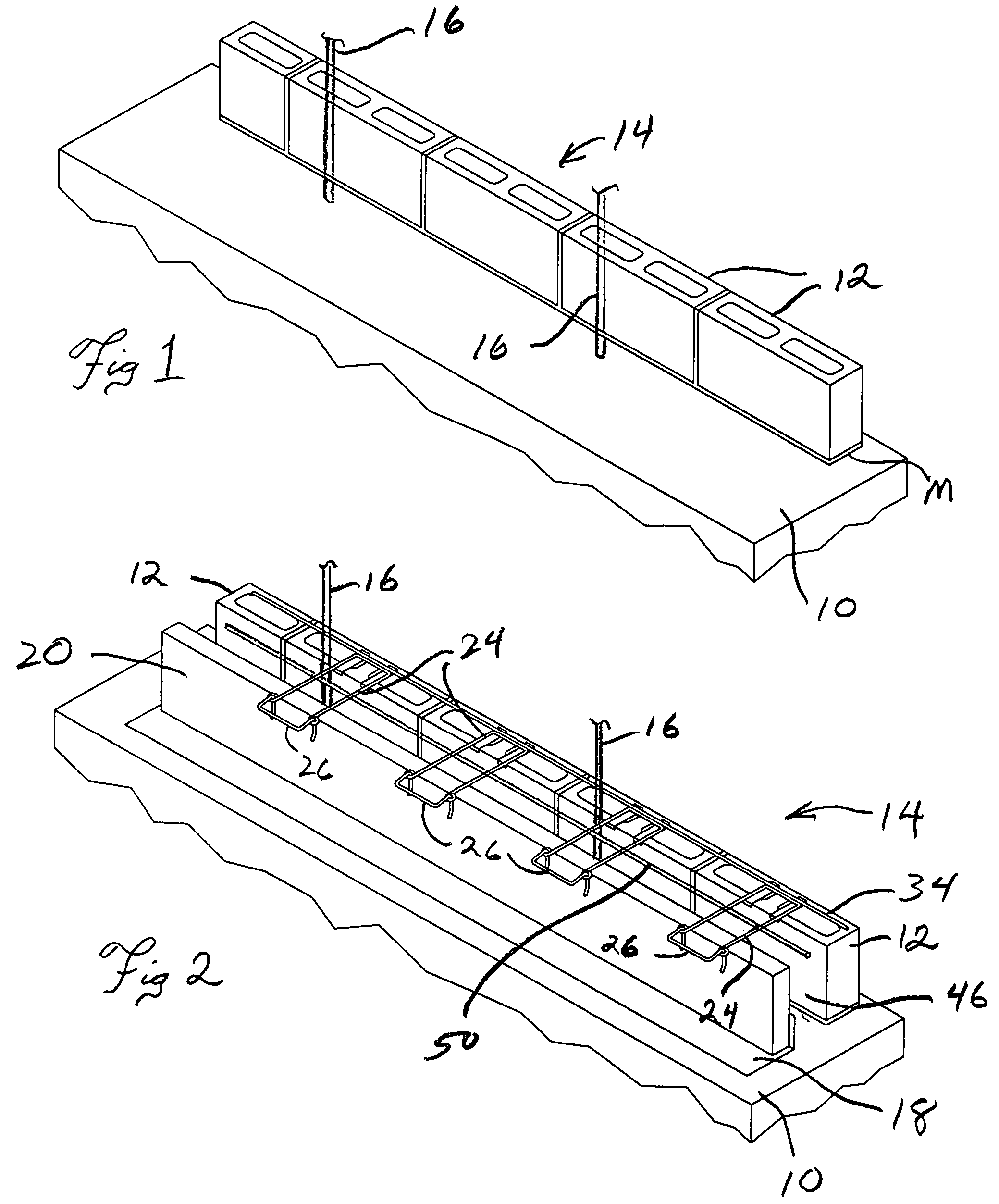
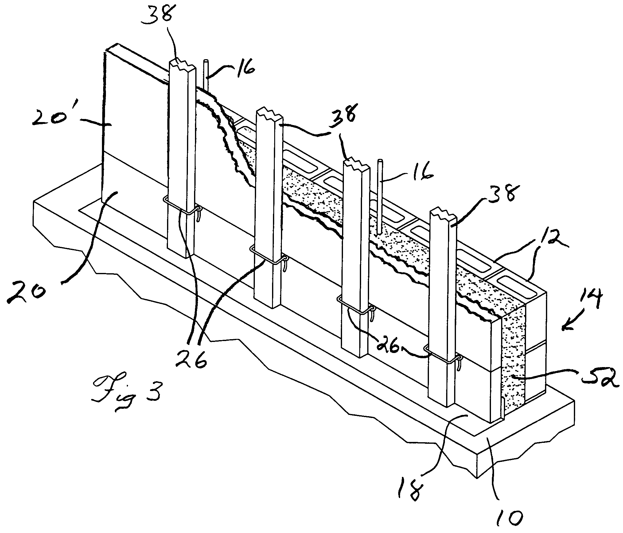
[0025]FIGS. 1-5 illustrate one example of a masonry cavity wall construction embodying features of the present invention in various successive stages during its construction. First, with reference to FIG. 1, a suitable foundation wall footing 10 is provided in typical manner as determined by the construction specifications for the building wall as is well understood in the art.

[0026]Then, using mortar M, the mason installs a first course of masonry units illustrated herein as concrete blocks 12 on the foundation footing 10 to the predetermined interior wall building line according to the building specification. This structure will eventually become the first, inner wythe 14 of the masonry cavity wall structure of this invention, the innermost side surface of which will form the interior wall of the building. For reference, the concrete blocks 12 illustrated herein are 4 inches thick, 8 inches tall and have a selected length dimension. Also, the foundation footing 10 may, as illustra...


PUM


Abstract

A masonry cavity wall structure includes a cast-in-place reinforced concrete structural wall member erected between and in confronting engagement with the outer side of a first, inner masonry wythe and the inner side of an outwardly spaced-away, upstanding wall of rigid insulation panels supported by wire tie members in embedded engagement in the mortar joints of the inner wythe, the inner wythe and tie-supported insulation panels also being used during construction of the cavity wall to provide the supporting concrete formwork for the poured structural wall member. A second, outer veneer wythe is erected a predetermined spaced distance outwardly from the insulation panels and forms an airspace cavity therebetween, the wire tie members also engaged in the mortar joints of the second, outer wythe whereby to structurally tie the masonry cavity wall together. The placement of the cast-in-place reinforced structural wall immediately adjacent the inner wythe and inwardly of the insulation provides maximum thermal mass qualities of the cavity wall construction.

Description

[0001]This application claims benefit under 35 U.S.C. 119(e) of the priority filing of U.S. Provisional application Ser. No. 60 / 671,976 filed 14 Apr. 2005.BACKGROUND OF THE INVENTION[0002]This invention relates to masonry walls used in the construction of buildings, and more specifically to the masonry cavity wall type of masonry wall construction.[0003]In masonry cavity wall construction a wall is typically constructed having two separate wythes with an intermediate space therebetween. Generally, the inner wythe is formed of concrete blocks and typically forms the structural, load-bearing component of the building wall structure. The outer face side of the inner wythe is provided with an insulation layer, commonly rigid foam panels or insulation board. A second, exterior or rain screen wythe is constructed a spaced distance outwardly of the insulation layer, the exterior wythe typically being a non-load bearing wall made of brick, stone or other masonry material. The open space lef...

Claims


Application Information

Patent Timeline
Patent Type & Authority Patents(United States)
IPC IPC(8): E04G21/00E04B1/16
CPCE04B1/4185E04B2/8652E04B2002/8688
Inventor MASSIE, MICHAEL C.
Owner MASSIE MICHAEL C
Why Eureka
Try Eureka