
Ink jet print head

a printing head and jet technology, applied in printing and other directions, can solve the problems of preventing the desired ejection performance and efficiency from being achieved, reducing the droplet size, increasing the scale of drivers and circuits, and thus cost, and achieving efficient and rapid printing.

Inactive Publication Date: 2010-06-15
CANON KK
View PDF24 Cites 6 Cited by
  • Summary
  • Abstract
  • Description
  • Claims
  • Application Information

AI Technical Summary

Benefits of technology

[0013]An object of the present invention is to provide an ink jet print head having a plurality of types of nozzles arranged on the same substrate and through which ink droplets of different sizes are ejected, the ink jet print head exhibiting acceptable ejection performance regardless of the type of nozzle to enable high-quality images to be efficiently and quickly printed.
[0015]According to the present invention, among the plurality of types of nozzles through which ink droplets of different sizes are ejected, even the nozzle through which small sized ink droplets are ejected can avoid being seriously affected by a manufacturing error in the ejection port portion. Therefore, the balance of the landing performance among the plural types of nozzles can be improved.

Problems solved by technology

However, the reduced opening area of the ejection port may increase the flow resistance to a liquid in a portion (ejection port portion) that communicates with the ejection port, preventing desired ejection performance and efficiency from being achieved.
However, the droplet size reduction has also been found to be disadvantageous in terms of costs, print speed, thermal efficiency, and the like.
This tends to increase the scales of drivers and circuits and thus costs.
Furthermore, an increase in nozzle length or chip count for high-speed printing also increases the costs.
Thus, the thermal efficiency of a printing operation tends to decrease.
However, for the conventional print head, which has the plural types of nozzles of different sizes, each having the ejection port portion composed of the first ejection port portion and the second ejection port portion as described above, ejection characteristics may disadvantageously be unbalanced among the nozzles.
This is likely to affect ejection performance such as the amount of ink droplets and landing accuracy.
Thus, a possible manufacturing error as described above unbalances the ejection performance between the nozzle with the large ejection port and the nozzle with the small ejection port.
This may in turn degrade the quality of images formed using a combination of the large and small dots.
Consequently, the suction recovery capability may be degraded, that is, old ink in the nozzle cannot be sufficiently discharged.
Namely, for the conventional print head, the nozzle through which smaller ink droplets are ejected is more likely to suffer degradation of the suction recovery capability.
This may also unbalance the ejection performance among the various nozzles, degrading the image quality.

Method used


Image

  • Ink jet print head
  • Ink jet print head
  • Ink jet print head

Examples


first embodiment

[0046]First, a first embodiment of the present invention will be described with reference to FIGS. 1, 2, 3A, 3B, and 3C.

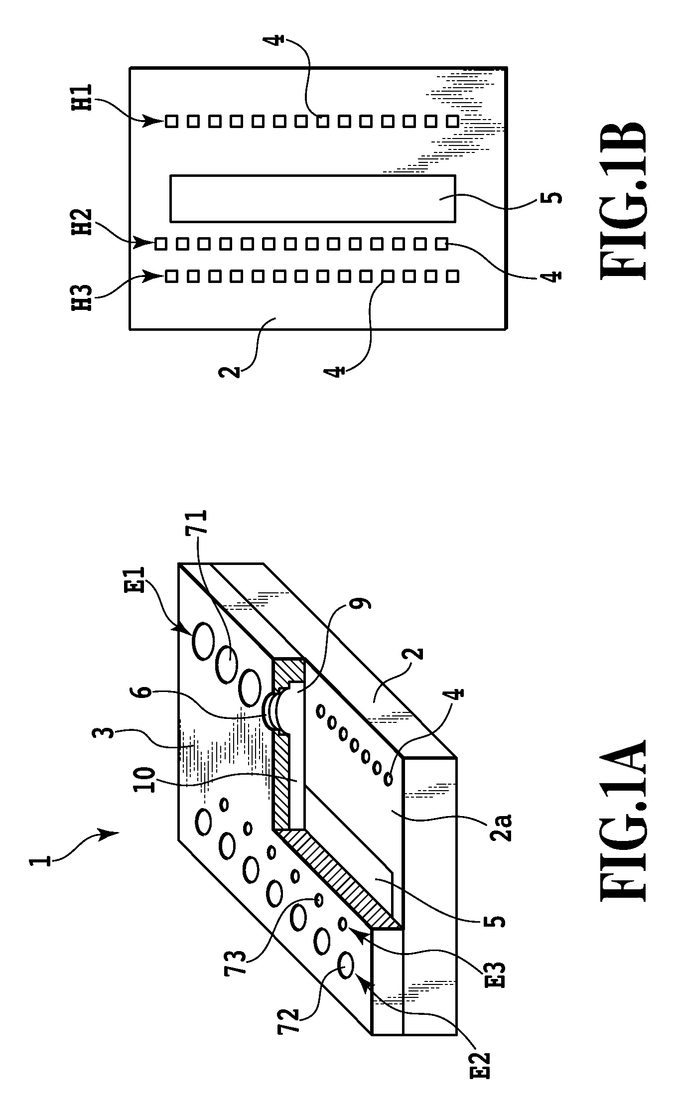
[0047]FIG. 1A is a partly cutaway perspective view schematically showing an ink jet print head 1 according to the first embodiment. The ink jet print head 1 comprises an element substrate 2 having electrothermal conversion elements 4 as ejection energy generating elements and a channel constituting substrate (orifice plate) 3 stacked on a major surface 2a of the element substrate 2.

[0048]As shown in FIG. 1B, three print element arrays H1, H2, and H3 each made up of a plurality of electrothermal conversion elements 4 are arranged on the element substrate 2 parallel to one another. An ink supply port 5 is formed between the first print element array H1 and both the second and third print element arrays H2 and H3.

[0049]A plurality of ejection port portions 6, a plurality of bubbling chambers 9, and a plurality of ink supply channels 10 are formed in the channel consti...

second embodiment

[0061]Now, a second embodiment of the present invention will be described.

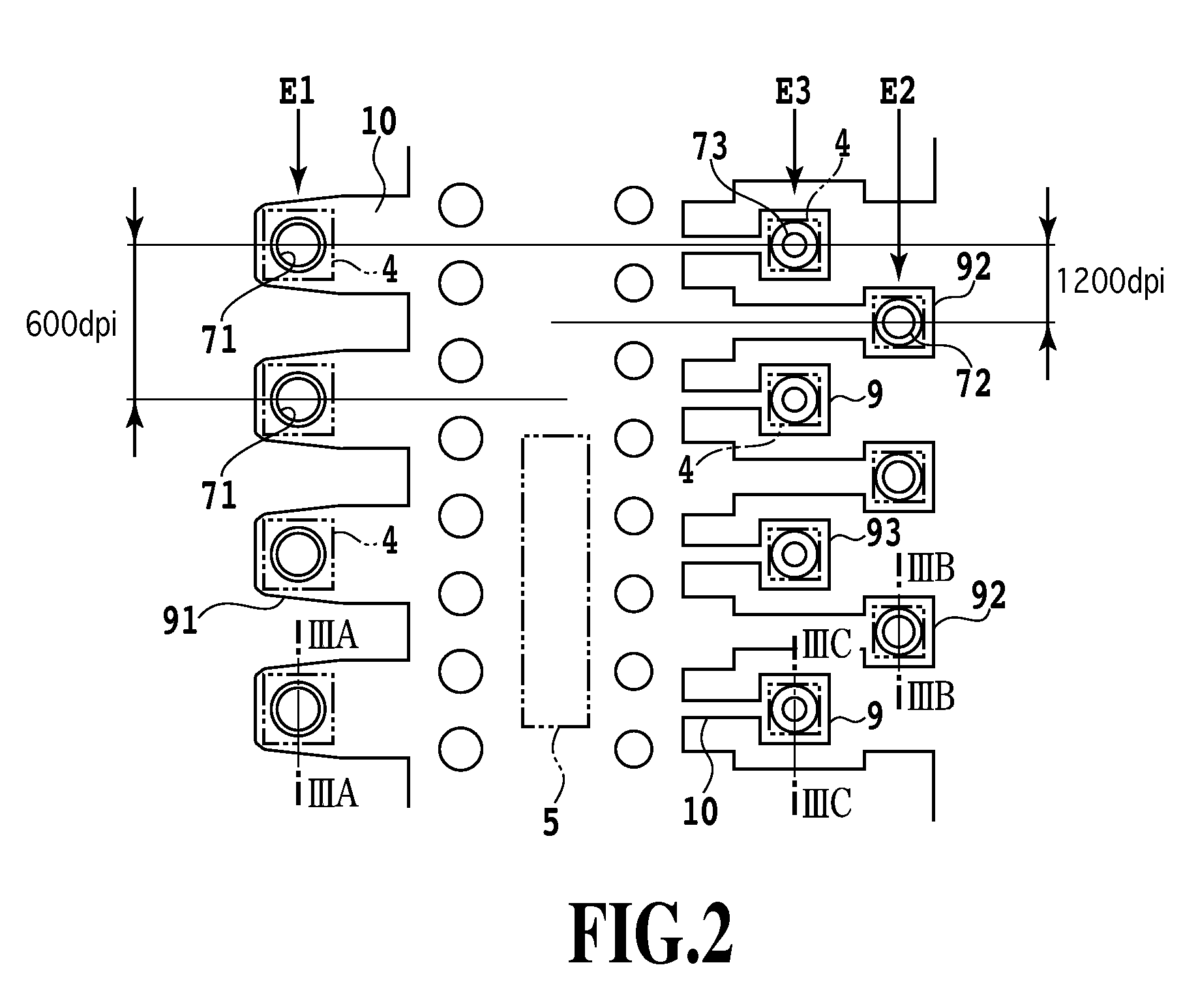
[0062]FIG. 4 is a bottom view of a part of ejection port arrays in an ink jet print head according to the second embodiment. FIG. 4 shows the positional relationship among the bubbling chambers 9, the ink supply channels 10, the electrothermal conversion elements 4, and the ejection ports 71, 72, and 73. In the second embodiment, the four ejection port arrays E1, E2, E3, and E4 are arranged parallel to one another. The first and second ejection port arrays E1 and E2 are arranged on one side (in the figure, on the left side) of the ink supply port 5. The third and fourth ejection port arrays E3 and E4 are arranged on the other side (in the figure, on the right side) of the ink supply port 5. Each of the first and third ejection port arrays E1 and E3 is composed of the large ejection ports 71, shown in FIG. 3A. The second ejection port array E2 is composed of the medium ejection ports 72, shown in FIG. 3B. The f...

third embodiment

[0066]A third embodiment of the present invention will be described.

[0067]In the second embodiment, all the ejection port portions are cylindrical. However, the ejection port portions need not necessarily be cylindrical but may have another shape. In the third embodiment, each of the ejection port portions is formed to have an elliptic cross-section.

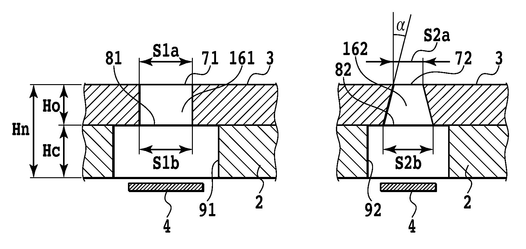
[0068]Also in the third embodiment, the liquid volumes Va, Vb, and Vc of large, medium, and small ink droplets are 2.8 ng, 1.4 ng, and 0.7 ng, respectively. The sectional areas S1a, S2a, and S3a of the ejection ports are about 120 nm2, 60 um2, and 30 um2. The ratios of the opening area of the second ejection port portion to the opening area of the ejection port, that is, S1b / S1a, S2b / S2a, and S3b / S3a, are 3.1, 3.6, and 6.3, respectively.

[0069]Consequently, the magnitude correlation between the ratios of the opening area of the second ejection port portion to the opening area of the first ejection port portion is as follows:

S1b / S1a2b / S2a3...


PUM


Abstract

An object of the present invention is to provide an ink jet print head having plural types of nozzles arranged on the same substrate and through which ink droplets of different sizes are ejected, the ink jet print head exhibiting acceptable ejection performance regardless of the type of the nozzle. Thus, according to the present invention, each of the plural types of nozzles includes a bubbling chamber having an ejection energy generating element allowing an ink droplet to be ejected to a position located opposite an ejection port and an ejection port portion allowing the ejection port and the bubbling chamber to communicate with each other. Ratio of opening area of the ejection port portion at a position where the ejection port portion and the bubbling chamber communicate with each other, to the opening area of the ejection port is higher for the nozzle with a smaller ejection amount.

Description

BACKGROUND OF THE INVENTION[0001]1. Field of the Invention[0002]The present invention relates to an ink jet print head that ejects ink droplets to print a print medium, and in particular, to an ink jet print head having a plurality of types of nozzles arranged on the same substrate and through which ink droplets of different sizes are ejected.[0003]2. Description of the Related Art[0004]With the increased operating speed of ink jet printing apparatuses and improved image quality provided by the ink jet printing apparatuses, attempts have been made to reduce the size of droplets ejected by print heads while increasing ejection frequency.[0005]A reduction in the size of ejected droplets requires a reduction in the opening area of each ejection port in the print head. However, the reduced opening area of the ejection port may increase the flow resistance to a liquid in a portion (ejection port portion) that communicates with the ejection port, preventing desired ejection performance an...

Claims


Application Information

Patent Timeline
Patent Type & Authority Patents(United States)
IPC IPC(8): B41J2/15B41J2/145
CPCB41J2/1404B41J2002/14475B41J2002/14403B41J2002/14387
Inventor MATSUMOTO, MITSUHIROKANEKO, MINEOTSUCHII, KENYAMANE, TORUOIKAWA, MASAKITOMIZAWA, KEIJIIDE, SHUICHITAKINO, KANSUINABESHIMA, NAOZUMI
Owner CANON KK
Learn More