Melting furnace with agitator

a technology of agitator and melting furnace, which is applied in the direction of checking devices, protective garments, chemical/physical processes, etc., can solve the problems of high power consumption, limited performance, and difficult maintenance, and achieves simple structure, low cost, and easy handling.

Active Publication Date: 2010-06-15
TAKAHASHI KENZO
View PDF3 Cites 11 Cited by
  • Summary
  • Abstract
  • Description
  • Claims
  • Application Information

AI Technical Summary

Benefits of technology

[0009]The present invention has been made in consideration of the above to make up for the shortcomings in the related art, and provides a melting furnace that is easily handled, has has simple structure, is able to be produced inexpensively and is able to be produced as both a small-sized furnace and a large-sized furnace.
[0011]According to the present invention, it is possible to provide a melting furnace that is easily handled, has simple structure, is able to be produced inexpensively and is able to be produced as both a small-sized furnace and a large-sized furnace.

Problems solved by technology

In this technique, there are shortcomings in that a ratio where power is converted into heat during the generation of the magnetic field is large, high power consumption is required, and it is difficult to perform maintenance.
This requires meticulous attention in operation, and is limited to small performance.

Method used


Image

  • Melting furnace with agitator
  • Melting furnace with agitator
  • Melting furnace with agitator

Examples


Embodiment Construction

[0023]The principle of the present invention will be described previously to the description of an embodiment of the present invention.

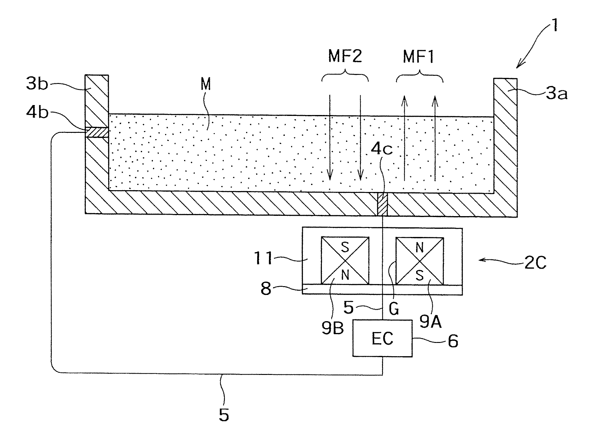
[0024]In the present invention, two magnetic field devices are used and an aluminum melt or the like is driven straight by a resultant force of electromagnetic forces of the magnetic field devices.

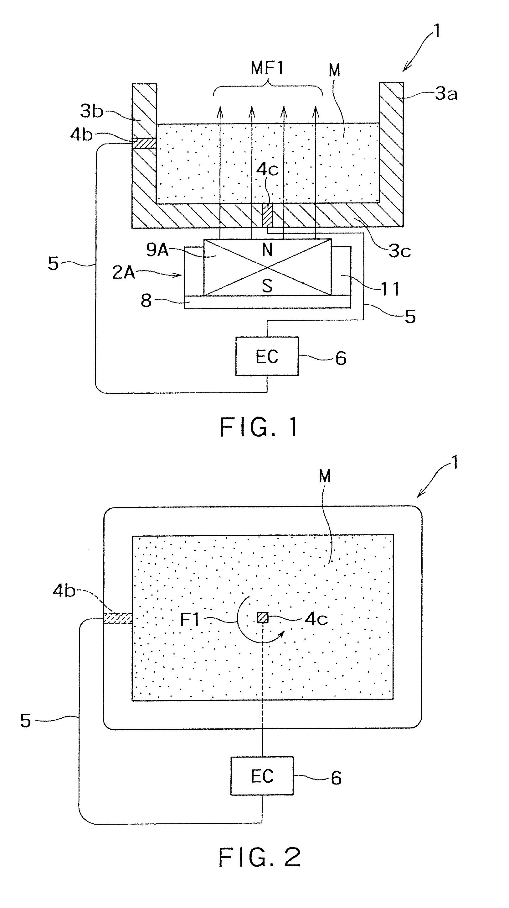
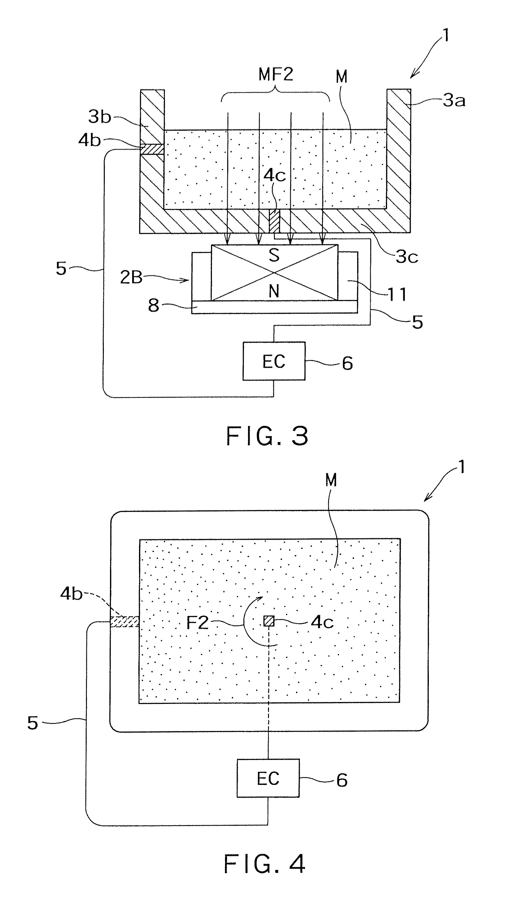
[0025]First, the drive principle using one magnet will be described.

[0026]An apparatus shown in FIGS. 1 and 2 is used to rotate a melt M in a direction of a flow F1 shown in FIG. 2. FIG. 1 is a longitudinal sectional view of the apparatus, and FIG. 2 is a plan view thereof.

[0027]In FIG. 1, reference numeral 1 denotes a melting furnace, and reference numeral 2A denotes an agitator. An electrode 4b is provided in a sidewall 3b of sidewalls 3a and 3b of a furnace main body 3 of a melting furnace 1, and an electrode 4c is also provided in a bottom wall 3c. These electrodes 4b and 4c are connected to a power supply (power supply control panel EC) 6 by cables 5. ...


PUM

PropertyMeasurementUnit
flow velocityaaaaaaaaaa
magnetic fieldaaaaaaaaaa
widthaaaaaaaaaa

Abstract

There is provided a melting furnace with an agitator. The melting furnace with an agitator includes a melting furnace that contains melt, and an agitator that agitates the melt by an electromagnetic force. The agitator includes a first electrode that is provided at an arbitrary position of the melting furnace so as to come in contact with the melt contained in the melting furnace, a second electrode that is provided near a bottom wall of the melting furnace so as to come in contact with the melt, a first magnetic field device that is provided outside the melting furnace so as to face the bottom wall of the melting furnace and makes a north pole face the bottom wall, and a second magnetic field device that is provided outside the melting furnace so as to face the bottom wall of the melting furnace and makes a south pole face the bottom wall. The first and second magnetic field devices are disposed with a gap in a certain direction.

Description

CROSS-REFERENCE TO PRIOR APPLICATION[0001]This application claims priority to Japanese Application No. 2008-169293, filed Jun. 27, 2008, the disclosure of each of which is incorporated herein by express reference thereto.BACKGROUND OF THE INVENTION[0002]1. Field of the Invention[0003]The present invention relates to a melting furnace with an agitator.[0004]2. Background Art[0005]In an automotive industry, an electric industry, and a building-products industry, aluminum has been widely used to make products in recent years. In each industry, strenuous efforts have been made to obtain an aluminum melt having uniform composition during the manufacture of products. In general, three main kinds of means have been used to achieve this object at present.[0006]First means is electromagnet type stirrer. In this technique, commercial power is used as energy for generating a magnetic field that is required for moving an aluminum melt. In this technique, there are shortcomings in that a ratio w...

Claims


Application Information

Patent Timeline
Patent Type & Authority Patents(United States)
IPC IPC(8): H05B6/32F27D27/00C21C7/00H05B6/54F27B3/10
CPCH05B6/34B01F13/0809F27B14/08C22B21/0084F27D27/00C22B9/003Y02P10/25B01F33/451A42B1/24A42B1/18A41D13/11
Inventor TAKAHASHI, KENZO
Owner TAKAHASHI KENZO
Why Eureka
Try Eureka