
Dual seal deposition process chamber and process

a technology of sealing process and process chamber, applied in the field of apparatus and processes, can solve the problems of reducing budget, void-free filling of high aspect ratio (ar) spaces (ar>3.0:1) becoming increasingly difficult, and shrinking dimensions

Active Publication Date: 2010-06-15
NOVELLUS SYSTEMS
View PDF48 Cites 305 Cited by
  • Summary
  • Abstract
  • Description
  • Claims
  • Application Information

AI Technical Summary

Benefits of technology

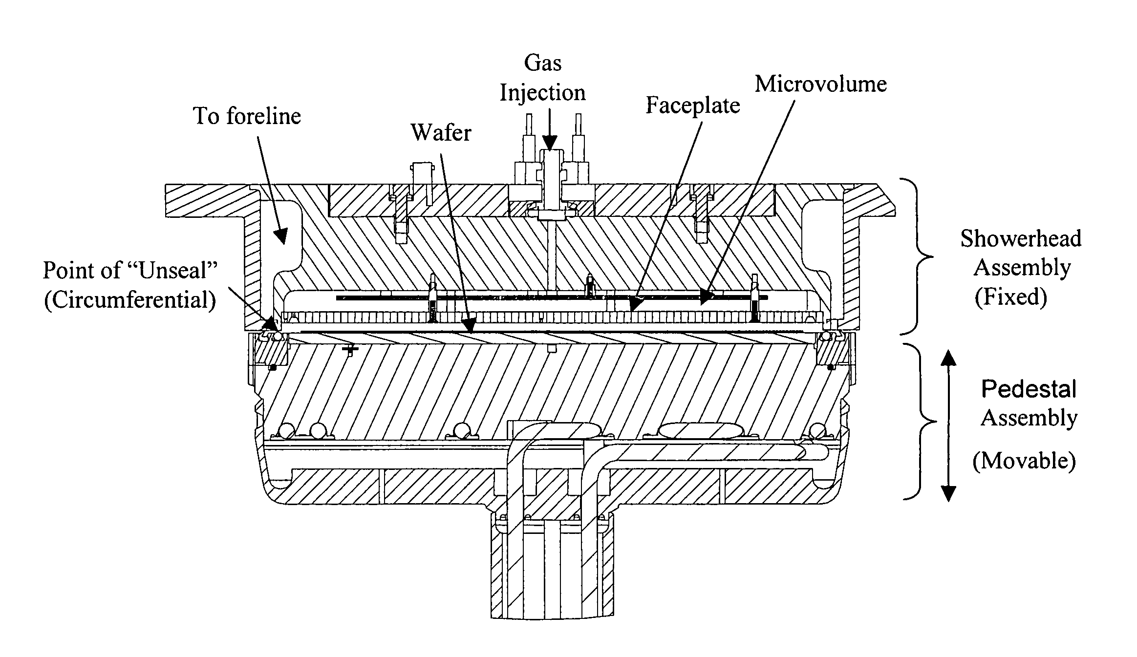
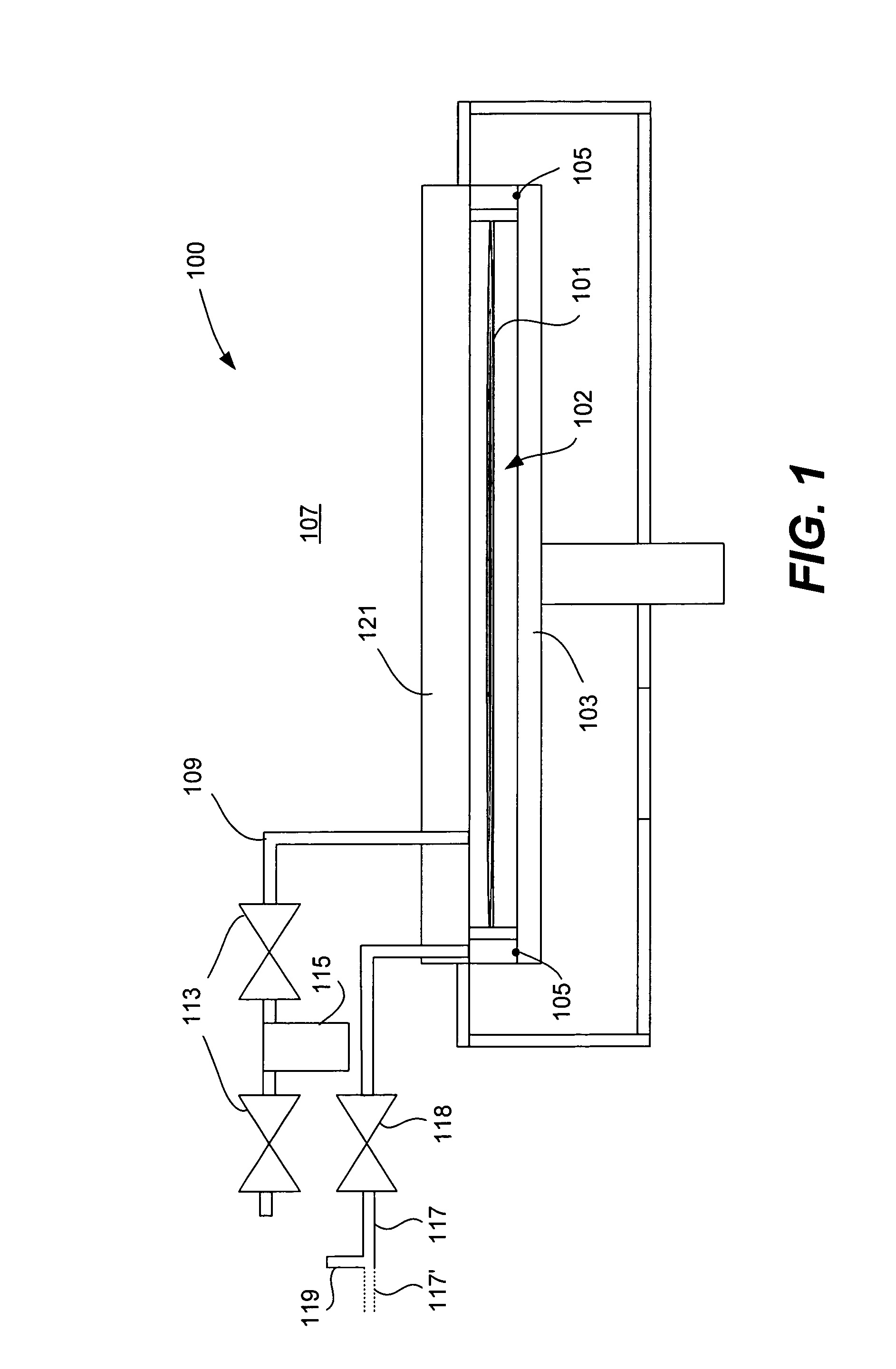
[0011]The present invention provides an apparatus and method for sealing and unsealing a chemical deposition apparatus. The apparatus includes a microvolume that has dual sealing elements at its periphery. One seal, the outer seal, is used to seal the inside of the volume from the main process chamber. The second (inner) seal is used to seal the inside of the microvolume from a vacuum source. The apparatus and process of the present invention has several advantages, including:
[0014]The dual-seal arrangement provides the sealing point very near the wafer edge allowing minimal chamber volume and reducing or eliminating dead legs (area that is a dead end without fluid flow through; that can become a refuge for by-products or particles that are very difficult to remove by purging the chamber). A very small deposition chamber volume in the form of the microvolumes formed by engagement of the pedestal and showerhead modules and operation of the dual seal also results in minimized chemical usage.
[0016]The dual-seal arrangement provides a vacuum path from the microvolume when only the outer seal is engaged. This greatly facilitates station isolation in multi-station reactors by minimizing the amount of precursor exposure to the main process chamber and helps avoid the need for an in situ clean.
[0017]The use of elastomeric seals to form the dual seal in various embodiments is mechanically simple, resulting in low cost and complexity of apparatus fabrication and operation, low maintenance and greater productivity.
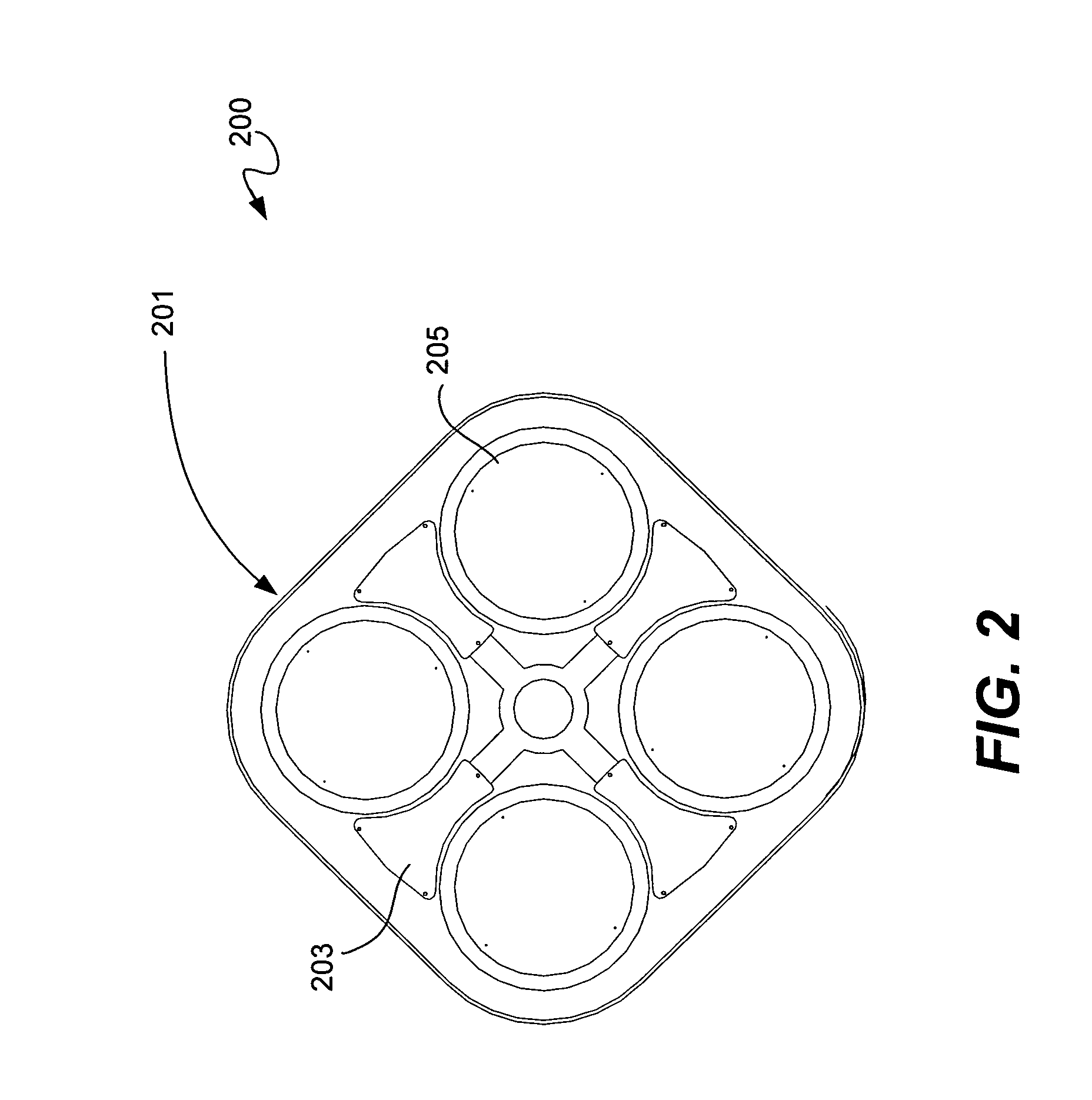
[0025]According to another aspect of the invention, in order to avoid wafer floating and / or backstreaming, particularly where a plurality of deposition chambers having the dual seal apparatus described above are combined in a multi-station deposition system (MDSS) reactor in which the plurality of deposition chambers share a common vacuum foreline for the evacuation apparatus, the inner seal can be opened gradually. Gradual opening of the inner seal prevents a sudden pressure release that can cause wafer float and / or backstreaming of the gas flow from one chamber to another.

Problems solved by technology

As device dimensions shrink and thermal budgets are reduced, void-free filling of high aspect ratio (AR) spaces (AR>3.0:1) becomes increasingly difficult due to limitations of existing deposition processes.
For structures representative of the 65 nm and 45 nm technology nodes and beyond, engineering the gap-fill process becomes structure dependent, hence the process requires re-optimization, a task of considerable complexity, every time a new structure needs to be filled.
One drawback, however, to ALD is that the deposition rates are very low.
These processes are unacceptably slow in some applications in the manufacturing environment.
When excess silanol is used, the film growth is usually self-limiting and a thick and uniform film results.
If these chamber cleans are not performed, the film stresses may be so large that the film delaminates from the chamber wall, leading to particle deposition on the wafer surface.
However, these chamber cleans reduce chamber productivity.

Method used


Image

  • Dual seal deposition process chamber and process
  • Dual seal deposition process chamber and process
  • Dual seal deposition process chamber and process

Examples


embodiment 600

[0069]In a preferred implementation of the dual circumferential elastomeric seal embodiment described with reference to FIGS. 4A-C and 5, above, the elastomeric seals and their associated mounting features on the pedestal, for example, module have a particular geometry. An example of this embodiment 600 is shown in FIG. 6. The mounting features for both seals are circumferential channels 602, 604 in the surface of the pedestal 606 that will engage with the showerhead module 608 to form the deposition microvolume. The channel 602 for the outer seal is configured with a reentrant feature 612 on the lower portion of its outer wall, and the outer elastomeric seal 614 is a lip seal configured with a corresponding tab 616, so that the channel feature 612 and the tab 616 fit together in a lock-and-key manner. This configuration retains the elastomeric seal 614 in place, preventing it from popping out of the channel 602 when the lip seal is engaged. The upper portion of the inner wall can a...

embodiment 700

[0070]FIG. 7 illustrates an alternative embodiment 700 of the invention in which a seal element 702 that has sealing surfaces on its top 704 and bottom surfaces 706 and is mounted on a flexible element 708 can be used to form the inner and outer seals. The flexible element 708, which may be metal, plastic or another suitable material, is mounted to the showerhead module 710. This design allows the first seal (outer seal, between the microvolume and the main reactor chamber) to be made when the pedestal 712 contacts the bottom surface 706 of the sealing element 710. The second seal (inner seal) is made when the pedestal travel (and / or travel of the showerhead module relative to the pedestal) deflects the flexible element 708 allowing the top surface 704 of the seal element to contact the showerhead 710, sealing off the vacuum source 714. The latter (fully closed) position of the seal and flexible elements is represented by the broken line 715 in the figure. Given these specifications...

embodiment 800

[0071]According to a third alternative, illustrated in FIGS. 8A-B in lateral and vertical cross-sections, respectively, a plurality of discrete valves arranged peripherally around the microvolume can be used in combination with a circumferential elastomeric seal to form the inner and outer seals of the dual seal, respectively. In this embodiment 800, the inner seal, between the vacuum source and the deposition region of the microvolume, is created by a plurality of discrete vacuum channels and valves in the showerhead module 803 arranged peripherally around the deposition region of the microvolume (which, in operation, contains the wafer 804); and the outer seal, between the microvolume and the main reactor chamber, is formed by a concentric elastomeric seal 806, such as an O-ring seal, on the surface of the pedestal module 805. In operation, the discrete vacuum channel valves 802 of the inner seal open or close together to promote uniform gas flow across the wafer 804 and correspon...


PUM

PropertyMeasurementUnit
Temperatureaaaaaaaaaa
Pressureaaaaaaaaaa

Abstract

An apparatus and method for sealing and unsealing a chemical deposition apparatus in a chemical deposition process chamber includes a microvolume that has dual sealing elements at its periphery. One seal, the outer seal, is used to seal the inside of the microvolume from the main process chamber. The second (inner) seal is used to seal the inside of the microvolume from a vacuum source. The apparatus and process of the present invention has several advantages for enhanced chamber performance.

Description

CROSS-REFERENCE TO RELATED PATENT APPLICATIONS[0001]This application claims priority under 35 USC 119(e) from U.S. Provisional Patent Application No. 60 / 788,262 filed Mar. 31, 2006, naming Lind et al. as inventors, which is incorporated herein by reference in its entirety.BACKGROUND OF THE INVENTION[0002]This invention pertains to apparatus and processes for conducting chemical depositions, and may find particular use in depositing a conformal film of dielectric material with a high degree of surface smoothness particularly suited to high aspect ratio gap fill applications in semiconductor device fabrication.[0003]Conformal, uniform dielectric films have many applications in semiconductor manufacturing. In the fabrication of sub-micron integrated circuits (ICs) several layers of dielectric film are deposited. Four such layers are shallow trench isolation (STI), premetal dielectric (PMD), inter-metal dielectric (IMD) and interlayer dielectric (ILD). Other applications of conformal di...

Claims


Application Information

Patent Timeline
IPC IPC(8): H01L21/44C23C16/00
CPCC23C16/4409Y10T29/41
Inventor LIND, GARYSMITH, COLIN F.JOHANSON, WILLIAMPRATT, THOMAS M.MAZZOCCO, JOHN
Owner NOVELLUS SYSTEMS
Learn More