Sealant gel for a telecommunication enclosure

a technology of sealing gel and enclosure, which is applied in the direction of coupling device connection, other chemical processes, instruments, etc., can solve the problems of gel melting and pooling, difficult to form a soft polyurethane gel that can withstand 120° c. heat-aging for a week, and most polyether-polyol-based sealant gels degrade, etc., to achieve excellent low-temperature performance, fast build up a hard backbone structure, and favorable mechanical properties

Active Publication Date: 2010-06-15
CORNING OPTICAL COMM LLC
View PDF20 Cites 21 Cited by
  • Summary
  • Abstract
  • Description
  • Claims
  • Application Information

AI Technical Summary

Benefits of technology

[0010]One aspect of the present invention is a sealant gel for a telecommunication enclosure such as a terminal seal used to terminate one or more ends of corresponding one or more telecommunication cables, such as fiber-optic cables and copper-wire cables. The sealant gel is formulated from at least three different polyols in a manner that maintains its favorable mechanical properties (e.g., its elastic and shear moduli and its viscosity) through environmental conditions, for example, over a wide temperature range. The first polyol is a polybutadiene-based polyol that has a low glass transition temperature that provides excellent low-temperature performance. The second polyol is a polyether polyol, which is very flexible and contributes the necessary viscoelastic properties. The third polyol is butene diol, which is a short molecule that quickly builds up a hard backbone structure that helps promote fast curing and provides resistance to cross-link network breakage at high temperatures.
[0011]The combined formulation for the sealant gel of the present invention builds up a well-balanced network structure that not only has all the necessary viscoelastic properties, but also withstands the highest required temperature of 120° C. while also exhibiting good performance at subzero temperatures.
[0012]Another aspect of the invention is a telecommunication enclosure that utilizes the sealant gel of the present invention. For example, one embodiment of such a telecommunication enclosure is a terminal seal where the sealant gel is contained in an endcap assembly arranged at one end of the terminal housing. The endcap assembly includes one or more openings through which corresponding one or more cable end portions can be inserted. The cable end portions are contained in an interior region of the housing below the end cap. The sealant gel in the endcap assembly conforms to the cable portion residing therein and makes sealing contact therewith so as to form a seal that prevents environmental contaminants from reaching the cable end portion that resides in the interior region. The sealant gel also makes sealing contact with the inside walls of the housing so as to complete the seal with respect to the interior region.

Problems solved by technology

While it is relatively easy to formulate a soft polyurethane gel that has good viscoelastic properties at ambient (room) temperature, it is extremely difficult to form a soft polyurethane gel that can withstand 120° C. heat-aging for a week.
However, most polyether-polyol-based sealant gels degrade when exposed to high temperatures for an extended period.
The degradation is a result of cross-linked network breakage, which causes the gel to melt and pool.
However, such gels become brittle at subzero temperatures.

Method used


Image

  • Sealant gel for a telecommunication enclosure
  • Sealant gel for a telecommunication enclosure
  • Sealant gel for a telecommunication enclosure

Examples


example telecommunication

Enclosure

[0035]The present invention includes a telecommunication enclosure that utilizes the sealant gel of the present invention as described above. An example telecommunication enclosure in the form of a terminal seal or “terminal” as mentioned above is now described. The description of the terminal as presented below is based on U.S. patent application Ser. No. 11 / 881,518 assigned to Corning Cable Systems, LLC and entitled “Terminal with internal environmental seal,” which patent application is incorporated by reference herein in its entirety.

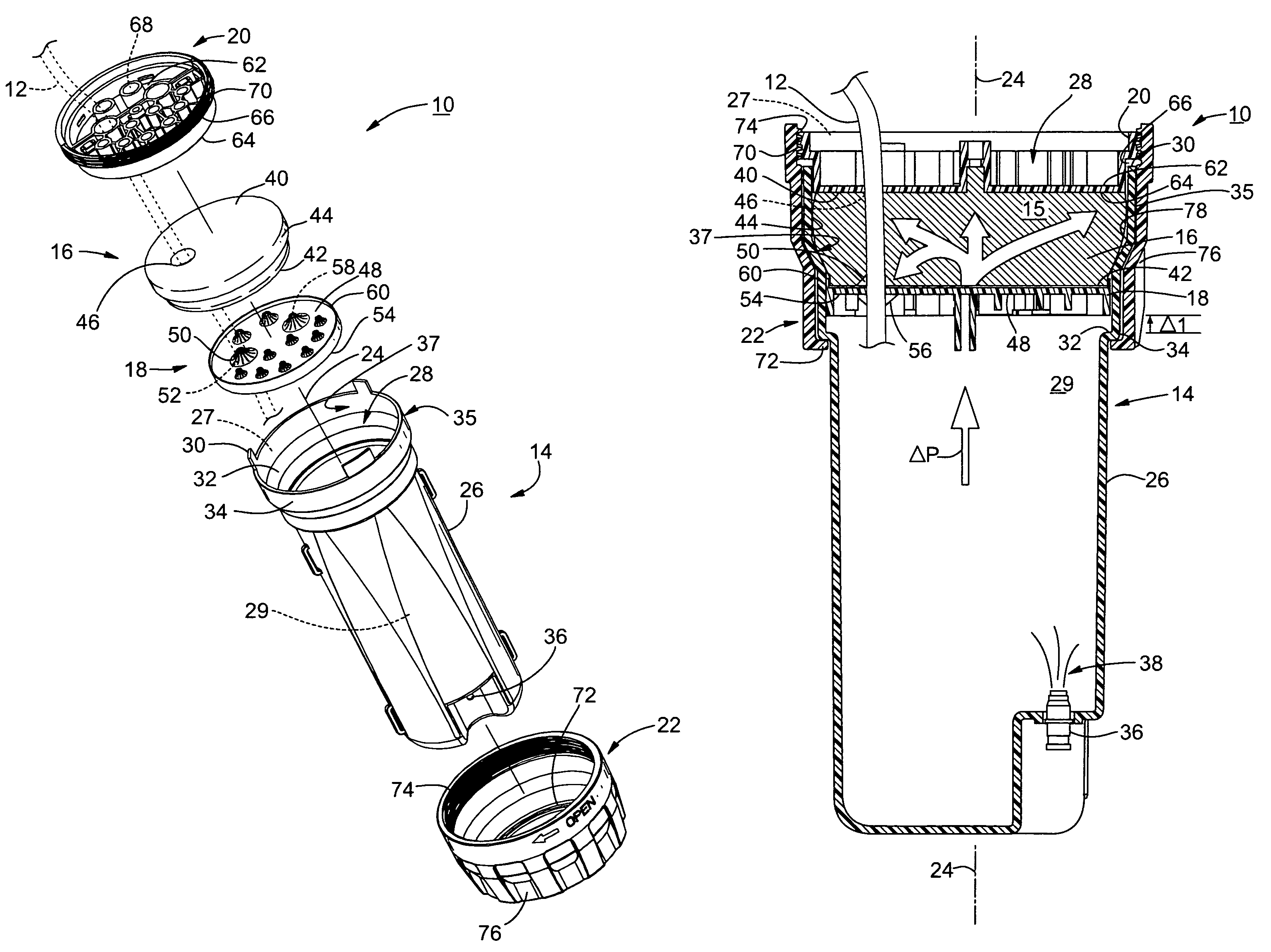
[0036]FIG. 4 is an exploded view of an environmentally sealed enclosure in the form of a fiber optic cable terminal 10. A fiber optic cable 12, which may be spliced, terminated or joined, is illustrated in phantom for clarity. An end portion of fiber optic cable 12 is sealed by fiber optic cable terminal 10. Further embodiments of the environmentally-sealed enclosure include one or more input members, such as fiber optic cables, copper cabl...


PUM

PropertyMeasurementUnit
temperatureaaaaaaaaaa
temperaturesaaaaaaaaaa

Abstract

A sealant gel for a telecommunication enclosure, wherein the gel is formulated from three different polyols. The first polyol is a polybutadiene-based polyol that has a low glass transition temperature. The second polyol is a polyether polyol. The third polyol is butene diol, which is a short molecule that quickly builds up a hard backbone structure.

Description

BACKGROUND OF THE INVENTION[0001]1. Field of the Invention[0002]The present invention relates generally to sealant gels, and in particular relates to a sealant gel for an enclosure used in a telecommunication system.[0003]2. Technical Background[0004]Telecommunication systems typically have a number of locations where copper wires and / or optical fibers are terminated and / or that are connected (e.g., spliced) to other wires and / or optical fibers. These terminations and connections are preferably made within enclosures that have a sealed interior to prevent degradation of the connections or of the unspliced terminal ends of the fibers and / or wires from the surrounding environment.[0005]For example, when fiber optic cables are spliced, the ends of the cables are often held within an enclosure called a “terminal seal” (or just “terminal” for short) to protect the ends of the cables and any connective equipment. Such terminals must cover and protect the cable ends from potential environm...

Claims


Application Information

Patent Timeline
Patent Type & Authority Patents(United States)
IPC IPC(8): H01R4/00
CPCC08G18/10C08G18/6674C08G18/69G02B6/4444H01R13/5216C09K3/1021C08K5/0016
Inventor HUSPENI, PAUL J.LIU, ZIWEI
Owner CORNING OPTICAL COMM LLC
Why Eureka
Try Eureka