

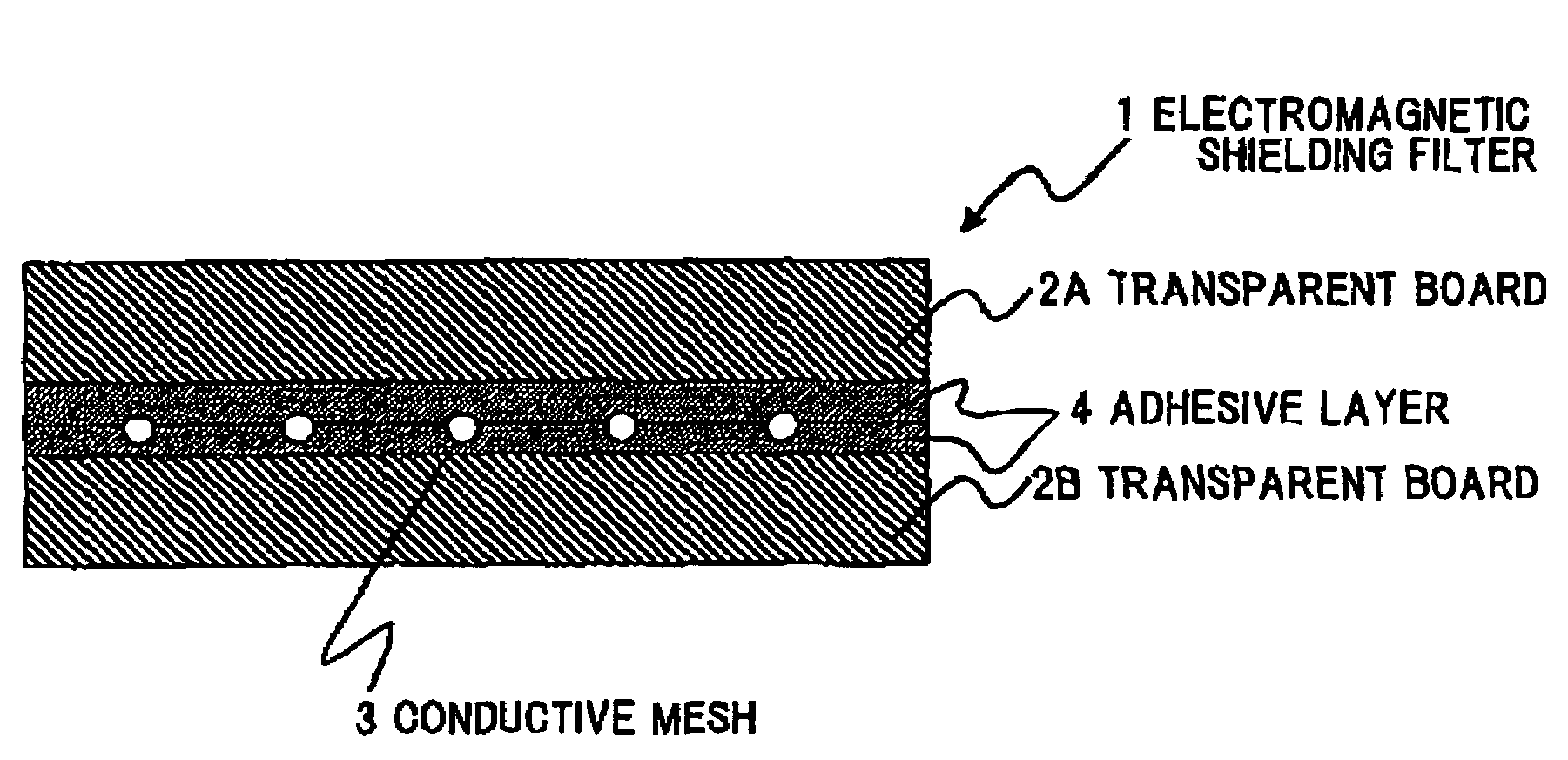
Electromagnetic shielding filter
a shielding filter and electromagnetic technology, applied in the direction of non-electron emission shielding screens, electric discharge tubes/lamp details, discharge tubes/lamp details, etc., can solve the problems of mechanical aspect, high production cost, and low electrical conductivity, and achieve low production cost, high tensile strength, and sufficient conductivity
- Summary
- Abstract
- Description
- Claims
- Application Information
AI Technical Summary
Benefits of technology
Problems solved by technology
Method used
Image

Examples
example 1
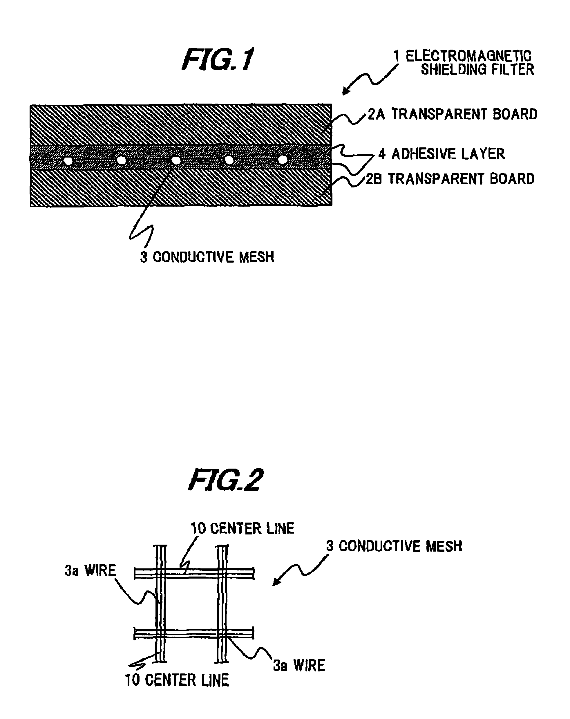
[0045]As a metal wire for composing a conductive mesh, a Cu-0.19 mass % Sn −0.20 mass % In alloy wire with a diameter of 20 μm φ is used. The alloy wire is previously Ag-plated on the periphery thereof. The mesh structure is formed such that the several alloy wires are aligned crosswise and the other several wires are aligned lengthwise orthogonally to the wires crosswise. The lattice obtained by the mesh structure has a side length of 300 μm and an aperture area of 87.1%. A long sheet of the mesh structure is wound on a take-up roll (mesh long sheet formation step).
[0046]Then, the mesh long sheet is fed out continuously from the roll while being aligned by a guide pulley, and is simultaneously sandwiched vertically by planar 0.05 mm PET films (transparent boards 2A, 2B) with a transparent adhesive layer wound on a bobbin. Then, the PET films are continuously bonded together by a rolling hot roll (at a rolling temperature of 150° C.) to produce the lengthy electromagnetic shielding ...
example 2
[0048]As the metal wire for composing the conductive mesh, a Cu-0.19 mass % Sn −0.20 mass % In alloy wire with a diameter of 16 μm φ is used. The mesh structure has an aperture area of 89.6%. The other conditions are the same as in Example 1 for producing an electromagnetic shielding filter of Example 2.
example 3
[0049]As the metal wire for composing the conductive mesh, a Cu-0.19 mass % Sn −0.20 mass % In alloy wire with a diameter of 13 μm φ is used. The mesh structure has an aperture area of 91.5%. The other conditions are the same as in Example 1 for producing an electromagnetic shielding filter of Example 3.
PUM
| Property | Measurement | Unit |
|---|---|---|
| thickness | aaaaa | aaaaa |
| thickness | aaaaa | aaaaa |
| diameter | aaaaa | aaaaa |
Abstract
Description
Claims
Application Information