
Method and device for 3 dimensional imaging of suspended micro-objects providing high-resolution microscopy

a technology of high-resolution microscopy and micro-objects, which is applied in the direction of microscopes, optical elements, instruments, etc., can solve the problems of physical limitations of light collection through glass lenses of any objective, limitations due to spatial resolution of images, and the inability to render three-dimensional maps of fluorescent signals from micro objects visualized by light microscopy. , to achieve the effect of reducing the calculation effort, reducing the loss of resolution, and optimal optical

Inactive Publication Date: 2010-06-15
PERKINELMER CELLULAR TECH GERMANY GMBH +1
View PDF21 Cites 34 Cited by
  • Summary
  • Abstract
  • Description
  • Claims
  • Application Information

AI Technical Summary

Benefits of technology

[0014]The object of the invention is to provide improved high-resolution measuring methods, in particular imaging methods avoiding the disadvantages of conventional methods. It is a particular object of the invention to provide a generally applicable solution that enhances high-resolution 3-D imaging methods by overcoming, diminishing or avoiding completely the systematic artifacts of light based microscopy described above. The invention shall provide an altogether new approach for the generation of three-dimensional image series describing both quantitatively and qualitatively a more accurate spatial map of any given fluorescent, bioluminescent, or auto-fluorescent micro-object—e.g. a live mammalian cell labelled with fluorescent molecules. Another object of the invention is to provide a device that may be implemented to any (and all) existing fluorescent microscope techniques (as described above).3) SUMMARY OF THE INVENTION
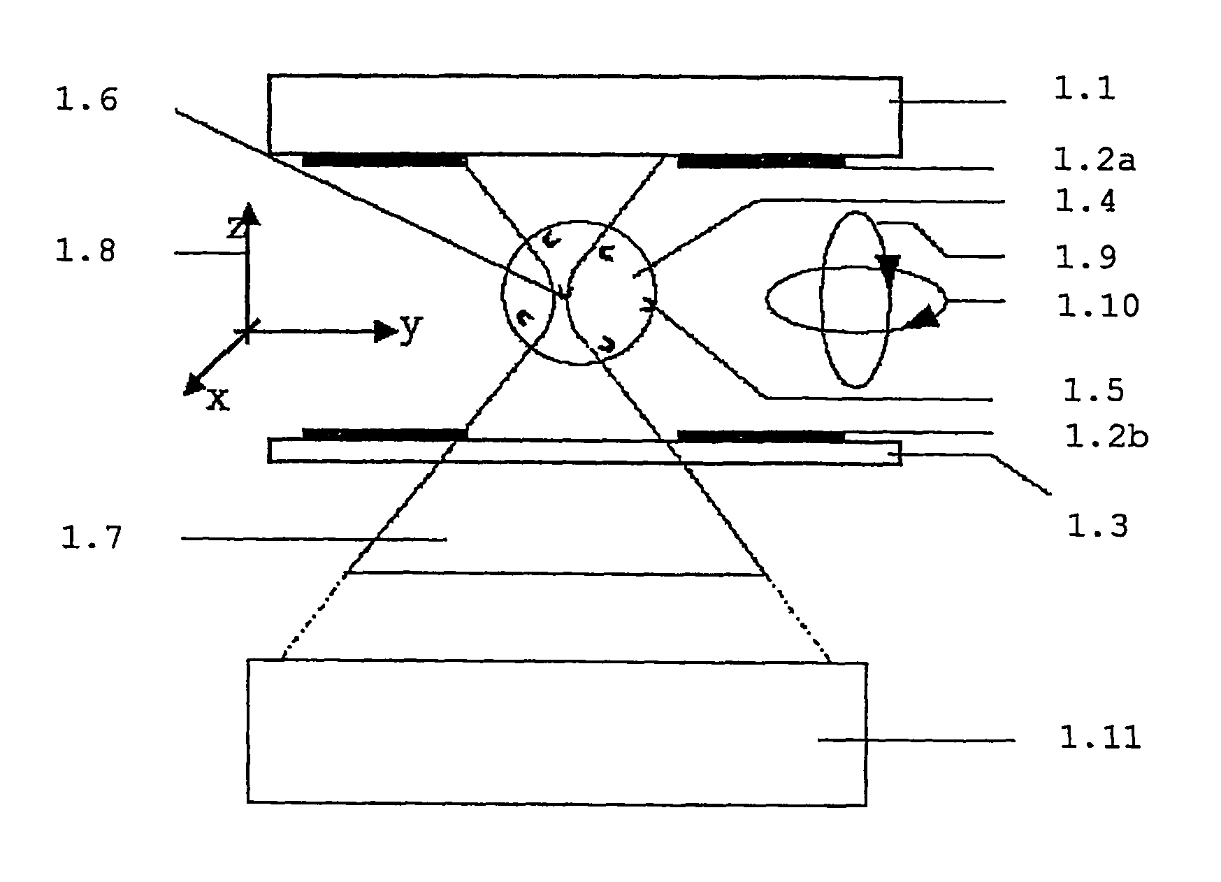
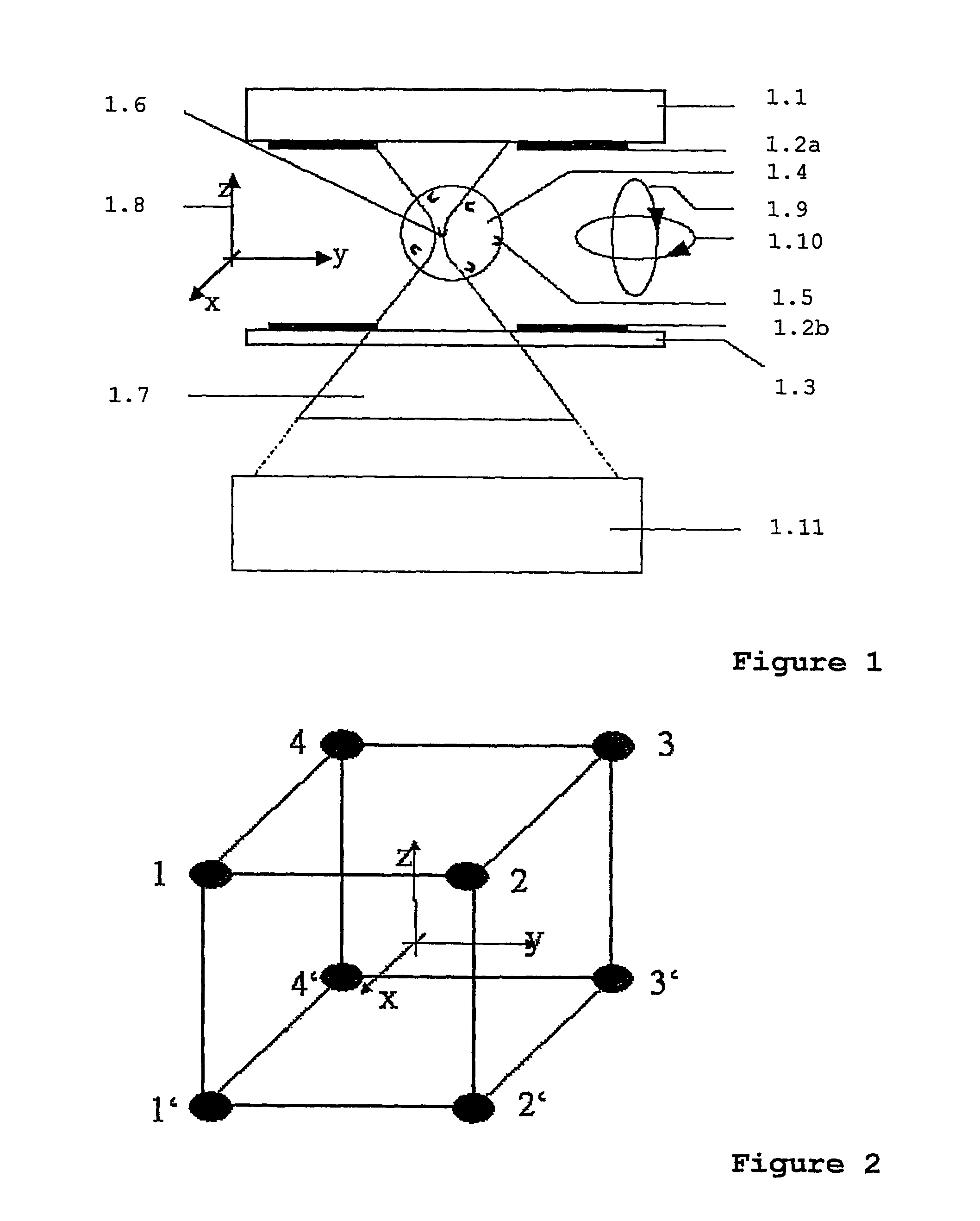
[0040]Further advantageous embodiments of the imaging system are characterized by a multi-electrode arrangement in the fluidic microsystem. The multi-electrodes arrangement comprises e.g. at least 3 electrodes within one plane surrounding the object. These electrodes can be controlled for an improved compensation of position or velocity variations of asymmetric objects.

Problems solved by technology

The ability to render three-dimensional maps of fluorescent signals from micro objects visualized by light microscopy is limited mainly by three systematic artifacts.
A central issue in light microscopy arises from limitations due to the spatial resolution of images.
However, there exist physical limitations for light collection through the glass lens of any objective.
In addition to the problems of optical aberration and diminished axial resolution that reduce the ability to visualize in 3-D on a light microscope, another problem is referred to as “chromatic aberration” or “axial chromatic aberration”.
The third problem of three-dimensional fluorescence microscopy is that the micro-object itself comprises a complex three-dimensional form, and as such interferes with image visualization from the focal plane.
This fact gives rise to a host of related problems for which there is no single general solution.
Nonetheless, these problems are inextricably linked and must be considered critically in order to achieve true three-dimensional rendering.
In general, these problems stem from light distortion caused by both the object itself, and the non-linear characteristics of light diffusion between different focal planes.
This light compromises the crispness of the image, inasmuch as it introduces an out-of-focus “haze” into the image focal plane.
Disadvantages of this approach are that it is calculation intensive (which costs time and processing power), and that it suffers inaccuracies and artifacts due to its extensive dependence upon calculation-based assumptions and / or corrections that must be applied at multiple stages during the processing procedure.
However, a major problem with applied algorithms using PSF, is that it is extremely difficult to measure a “good” PSF.
In particular, a major problem arises from the fact that the PSF in any given sample is itself altered as a function of the axial distance through the sample (Sedat).
This gives rise to a further group of problems, whereby light emission from the focal plane is deteriorated due to shading or diffraction do light by optically dense regions within the object itself (e.g. cell) that lay in between the microscope lens and the fluorescent features being imaged.
Note that this approach still suffers from chromatic and axial aberration problems.
The disadvantage of multi photon fluorescence microscopy is the requirement for high energy pulsed lasers to be attached to the microscope, resulting in high cost and large, difficult to manage equipment assemblage, maintenance and application.
Both methods bring along substantial limitations for the sample carrier and the microscope objective, which can be used.
In addition there is a huge effort involved when aligning the two focal volumes of the objective lenses, which has to be done with sub-micrometer precision.
Rotational fields had only limited trapping efficiency and were very sensitive to hydrodynamic streaming (Schnelle, Th. et al.

Method used


Image

  • Method and device for 3 dimensional imaging of suspended micro-objects providing high-resolution microscopy
  • Method and device for 3 dimensional imaging of suspended micro-objects providing high-resolution microscopy
  • Method and device for 3 dimensional imaging of suspended micro-objects providing high-resolution microscopy

Examples


examples

Imaging Experiments Performed with a Prototypic Set-Up Based on the Invention

—A—Visualization of the Lamin Structure of HeLa Cells

[0068]As an example for studying a cellular protein by live three-dimensional microscopy fluorescent nuclear lamin proteins inside a live suspended cell were imaged using a prototype of the invention.

[0069]Lamins are the major components of the nuclear lamina, a two-dimensional filamentous network at the periphery of the nucleus in higher eukaryotes, directly underlying the inner nuclear membrane. In the course of cell-cycle-dependent dynamics of the nucleus in higher eukaryotes, lamins as well as lamin-binding proteins seem to possess important functions during various steps of post-mitotic nuclear reassembly and seem to play a role in various pathological processes in muscle (Emery-Dreifuss muscular dystrophy, EDMD; dilated cardiomyopathy and conduction system defect, DCM-CD; and limb-girdle muscular dystrophy, LGMD) and adipose tissue (Dunnigan-type fa...


PUM

PropertyMeasurementUnit
angleaaaaaaaaaa
distanceaaaaaaaaaa
sizeaaaaaaaaaa

Abstract

A method for high-resolution image recording of at least one object with a microscope, includes the steps of: (a) positioning the object in a receptacle being arranged in the optical axis of the microscope, (b) generating at least two first data sets per object which represent intermediate images of the object with at least two different orientations relative to the optical axis of the microscope, wherein the different orientations of the object are provided by moving the object relative to the receptacle, and (c) evaluating the data sets for obtaining quantitative three dimensional information.

Description

[0001]The invention is related to methods and devices for high-resolution image recording of at least one object, in particular with a microscope.1) THE BACKGROUND OF THE INVENTIONA) Microscopy—in Biological Research.[0002]The development of fluorescent bio-molecular probes—especially fluorescent proteins enabling the observation of sub-cellular process and structure inside living cells, has come to pass as a renaissance in light microscopy. Now a variety of evolving bio-chemical techniques incorporate and / or are based upon combining fluorescent molecular probes and light microscopy. They provide both qualitative and quantitative visualization of specific molecular dynamics underlying live cellular activities. However, inasmuch as it is now clear that these biological processes depend upon spatio-temporal compartmentalization, the major focus for development in light microscopy, is to overcome certain systematic problems that obstruct our ability to render simple, yet quantitatively...

Claims


Application Information

Patent Timeline
Patent Type & Authority Patents(United States)
IPC IPC(8): G06K9/00G01N15/14G02B21/22G02B21/36
CPCG02B21/367G02B21/22G01N2015/144G01N2015/1445G01N2015/1452
Inventor SHORTE, SPENCERMULLER, TORSTENSCHNELLE, THOMAS
Owner PERKINELMER CELLULAR TECH GERMANY GMBH
Learn More