
Systems and methods for calibrating power regulated communication circuitry

a communication circuit and power regulated technology, applied in power management, transmission monitoring, transmission monitoring, etc., can solve the problems of wandering output power level output power level output power level, and the calibration process can be even more time-consuming

Inactive Publication Date: 2010-06-15
MARVELL ASIA PTE LTD
View PDF4 Cites 22 Cited by
  • Summary
  • Abstract
  • Description
  • Claims
  • Application Information

AI Technical Summary

Benefits of technology

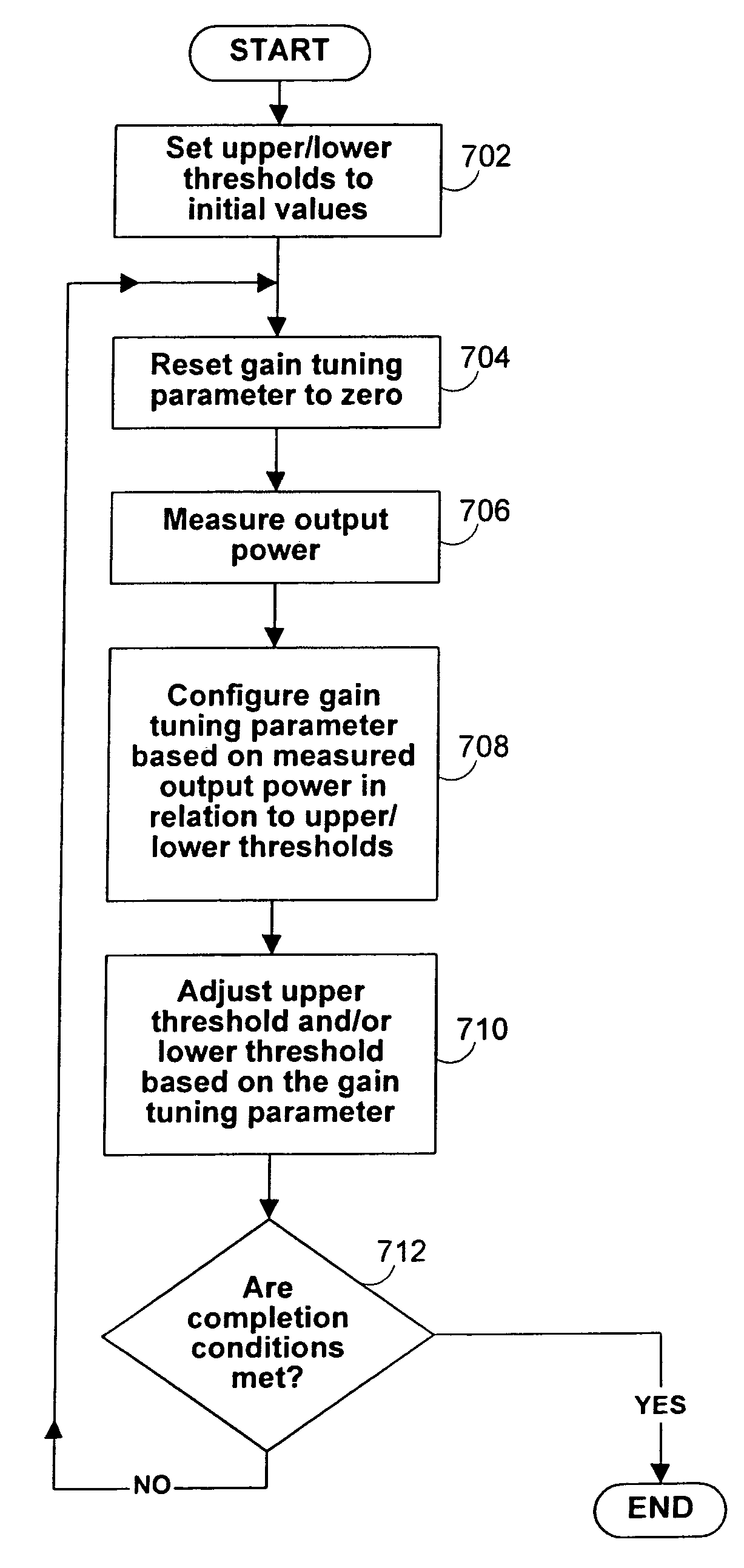
The patent describes a system and method for calibrating the control mechanism of a communication circuit to maintain a desired output power level. The system includes a variable gain adjustment circuit and a power amplifier, which work together to provide the desired output power level. A power detector measures the output power level and a calibration circuit adjusts the default gain parameter and the upper and lower power thresholds to achieve the desired power output. The calibration circuit can calibrate the default gain parameter and the upper and lower power thresholds while the feedback loop is enabled, and can use a table of adjustment values to iteratively adjust the thresholds. The technical effect of the patent is to provide a more accurate and stable output power level for communication circuits.

Problems solved by technology

Additionally, communication device manufactures may also have reasons to produce signals having particular power levels.
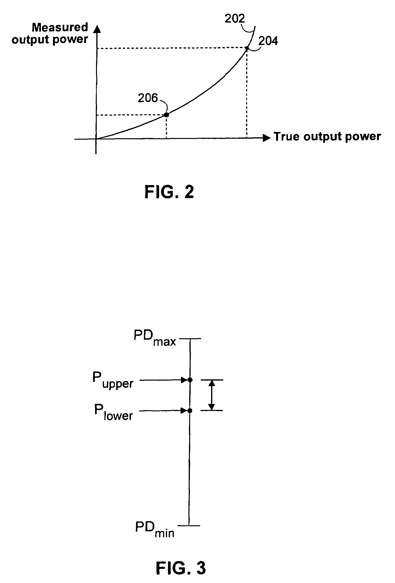
Such factors may cause the output power of the output power level to wander from a prescribed / target power level.
The calibration process can be even more time consuming when a communication device operates at multiple power levels.

Method used


Image

  • Systems and methods for calibrating power regulated communication circuitry
  • Systems and methods for calibrating power regulated communication circuitry
  • Systems and methods for calibrating power regulated communication circuitry

Examples


Embodiment Construction

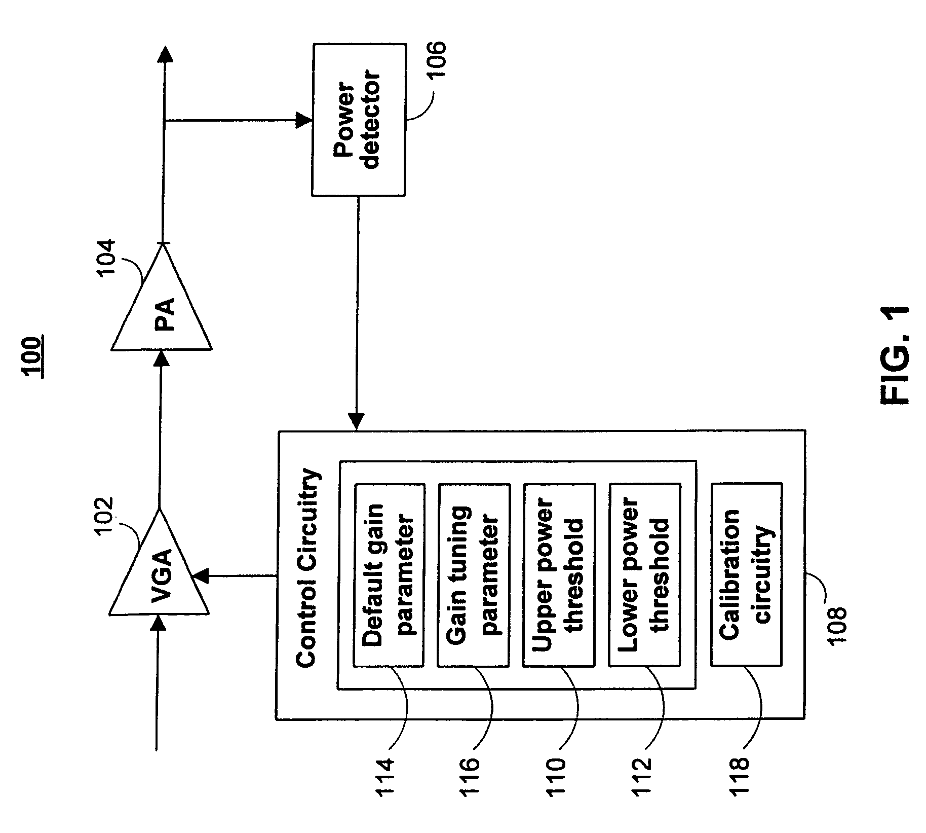
[0046]Referring to FIG. 1, there is shown a block diagram of one embodiment of a communication circuit 100 in accordance with one aspect of the invention. The communication circuit 100 includes a variable gain adjustment (VGA) circuit 102 and a power amplifier 104. As used herein, a variable gain adjustment circuit 102 refers to a circuit that operates to receive an input signal and that is operable to adjust an amplitude of the input signal. The adjustment may increase the amplitude, which is referred to as gain, or may decrease the amplitude, which is referred to as attenuation. Attenuation produces the opposite effect of gain and therefore can essentially be characterized as “negative gain.” Accordingly, the term “variable gain adjustment” as used herein refers generally to signal adjustment that can correspond to positive gain or negative gain (i.e., attenuation). As used herein, the term “power amplifier” refers to a circuit that receives an input signal and that is operable to...


PUM


Abstract

Systems and methods are provided for calibrating the control mechanism in a communication circuit to allow the communication circuit to maintain a desired output power level. The communication circuit includes a variable gain adjustment circuit and a power amplifier, which operate together to provide an output power level. A control circuit controls the variable gain adjustment circuit based on a default gain parameter, a high power threshold, and a low power threshold. A calibration circuit in the control circuit calibrates a default gain parameter to provide a desired output power. A power detector can detect the desired output power level to provide an output power measurement. The calibration circuit calibrates upper and lower power thresholds to provide an acceptable range of power variation around the output power measurement.

Description

CROSS-REFERENCE TO RELATED APPLICATIONS[0001]This application claims the benefit under 35 U.S.C. §119(e) of U.S. Provisional Application No. 60 / 695,342, filed Jun. 30, 2005, U.S. Provisional Application No. 60 / 708,901, filed Aug. 17, 2005, U.S. Provisional Application No. 60 / 775,965, filed Feb. 22, 2006, and U.S. Provisional Application No. 60 / 798,270, filed May 4, 2006, which are incorporated herein by reference in their entirety.BACKGROUND OF THE INVENTION[0002]This invention generally relates to wireless communication circuitry and more particularly to systems and methods for calibrating the output power control system in a wireless communication circuit.[0003]Wireless communication devices generally operate based on power requirements defined by government regulations or industry standards. Such standards and regulations may require a wireless communication device to produce signals having a prescribed power level. Additionally, communication device manufactures may also have re...

Claims


Application Information

Patent Timeline
Patent Type & Authority Patents(United States)
IPC IPC(8): H04B7/00
CPCH04W52/52H04B17/13H04B17/102Y02B60/50
Inventor CHIEN, GEORGETSAI, KING CHUNSON, SANG WONSHIRVANI-MAHDAVI, ALIREZASUN, QIONGLIM, LEYCHEOH
Owner MARVELL ASIA PTE LTD
Learn More