Adaptive retarder control method and apparatus

a technology of retarder and control method, applied in the direction of instruments, analogue processes for specific applications, electric/magnetic computing, etc., can solve the problems of reducing the working life of the service brake, slowing the vehicle, and the device may not be optimal,

Active Publication Date: 2010-06-15
ALLISON TRANSMISSION INC
View PDF7 Cites 11 Cited by
  • Summary
  • Abstract
  • Description
  • Claims
  • Application Information

AI Technical Summary

Benefits of technology

[0009]In another aspect of the invention, a method is provided for precisely controlling the rate of deceleration of a vehicle having a transmission with a rotatable output member and a retarder configured to retard the speed of the rotatable output member, including measuring the actual output speed of the output member, determining a desired output speed using a plurality of user-commandable speed input devices, communicating the actual output speeds to a controller, and commanding the retarder to apply a variable amount of retarder torque to the rotatable output member based on the actual and desired output speeds to thereby achieve a controlled rate of deceleration.

Problems solved by technology

Without the use of a transmission output speed retarder, a conventional vehicle braking system operating continuously under such aggressive slope or traffic conditions may tend to wear more rapidly, potentially reducing the working life of the service brake.
Likewise, electrodynamic / electric retarders produce a magnetic field in an opposite rotational direction to that of the driveshaft, thus slowing the vehicle.
However, such devices may be less than optimal, as they generally require an operator to actuate a retarder mechanism each time the operator wishes to engage the retarder.
Likewise, such mechanisms may provide inadequate vehicle speed control, as a given vehicle's rate of deceleration will necessarily vary along with its gross weight and / or axle ratio as the vehicle travels over different terrain and through various traffic conditions, thus requiring frequent retarder adjustments in order to maintain even a generally constant speed.

Method used


Image

  • Adaptive retarder control method and apparatus
  • Adaptive retarder control method and apparatus
  • Adaptive retarder control method and apparatus

Examples


Embodiment Construction

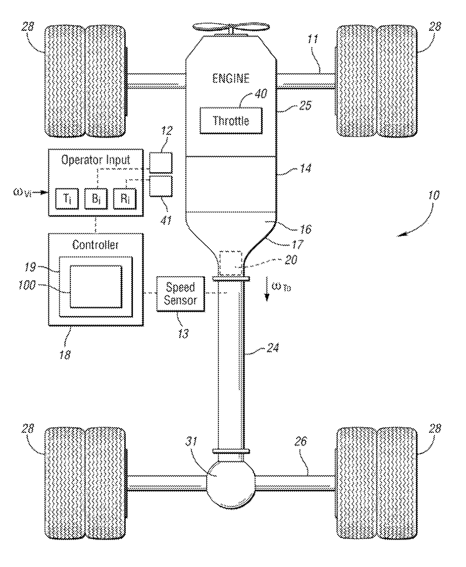
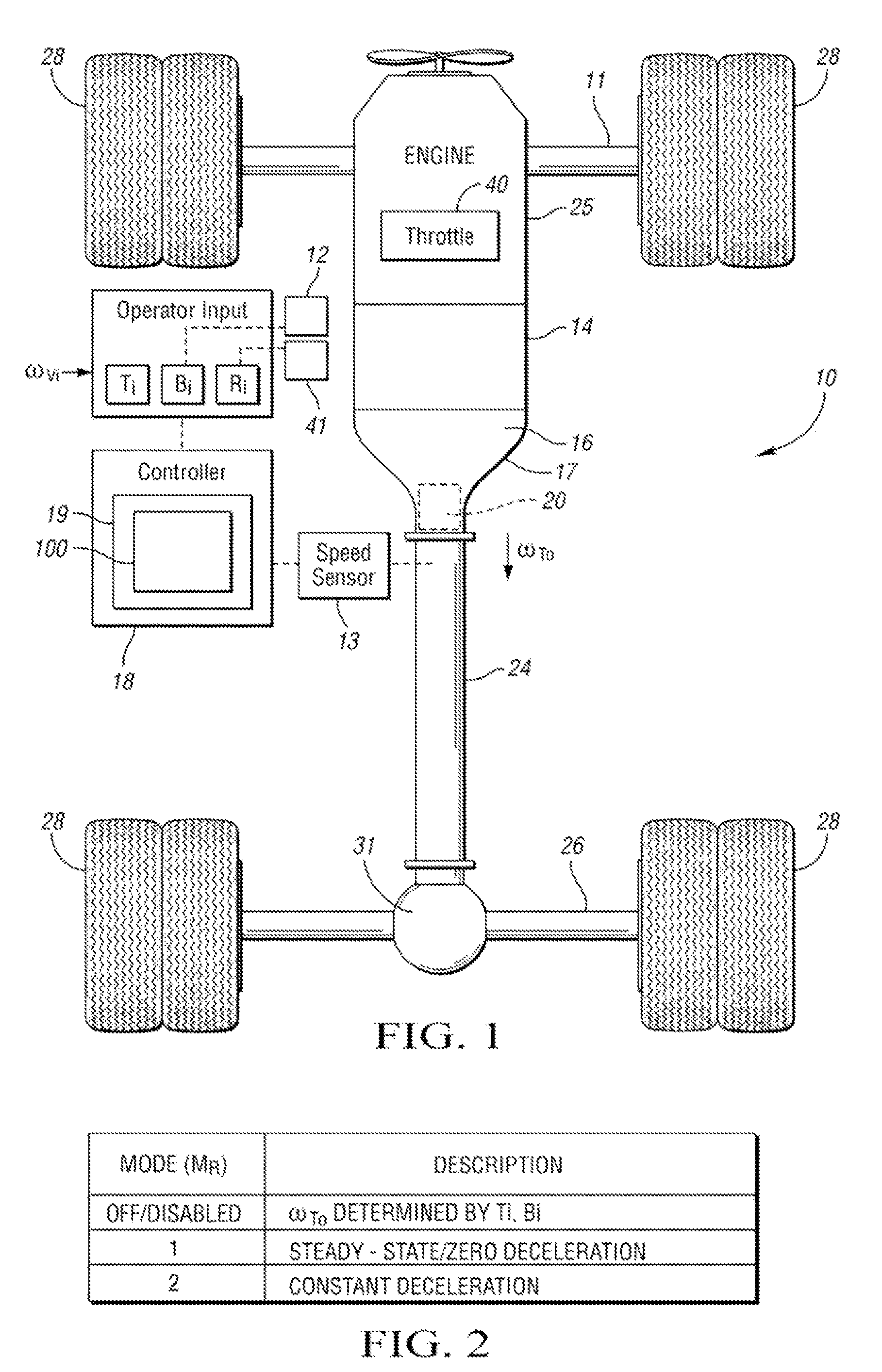
[0015]Referring to the drawings wherein like reference numbers correspond to like or similar components throughout the several figures, there is shown in FIG. 1 a schematic representation of a vehicle chassis 10 having a brake 12, a retarder selector switch 41, and an engine 25 with a throttle 40, with the throttle 40 preferably being selectively actuated by an accelerator pedal (not shown). The engine 25 is selectively connectable to a transmission 16 through a conventional hydrodynamic torque converter 14. The transmission 16 is operatively attached to a speed retarding mechanism or retarder 20, with the retarder 20 preferably being positioned within a transmission case or housing 17. The transmission 16 is configured to deliver a variable transmission output speed ωTo to a rotatable output member 24, such as a driveshaft, with the transmission output speed ωTo being detectable, measurable, or otherwise determinable by a speed sensor 13 attached directly or in proximity to the out...


PUM


Abstract

A vehicle transmission retarder control apparatus is provided including an engine, a throttle, a brake, a transmission having an output member with an actual transmission output speed, a speed sensor operable for measuring the actual transmission output speed, a plurality of user-commandable input devices for selecting a desired transmission output speed, and a controller having an algorithm for controlling the amount of retarder request to provide a zero or constant rate of deceleration independently of weight and axle ratio. Additionally, a method is provided for controlling a transmission retarder, including measuring the actual transmission output speed, sensing a desired transmission output speed using a plurality of user-commandable input devices, communicating the actual and desired speeds to a controller, and commanding the retarder to apply a continuously variable opposing torque to the transmission based on the actual and desired output speeds to achieve a constant rate of deceleration.

Description

TECHNICAL FIELD[0001]The present invention relates to a control apparatus and method for use with a vehicle speed retarder utilizing closed-loop and adaptive control logic configured to alternately provide steady-state and zero deceleration irrespective of the vehicle's weight and axle ratio.BACKGROUND OF THE INVENTION[0002]Transmission output speed retarders are non-wearing auxiliary braking devices used in conjunction with a rotatable vehicle transmission output member or driveshaft in order to safely augment the conventional friction-based braking system or service brakes used on certain large vehicles, such as diesel-powered medium and heavy trucks or busses. Such speed retarding devices or retarders are useful in helping to slow or stop a vehicle, particularly under continuous-braking or start-stop conditions and while the vehicle is descending a relatively long, steep slope, such as a descending stretch of mountain highway. Without the use of a transmission output speed retard...

Claims


Application Information

Patent Timeline
Patent Type & Authority Patents(United States)
IPC IPC(8): G06F17/00B60W30/18
CPCB60T10/02B60W10/02B60W10/196Y10T477/653B60W30/18136B60W2030/18081Y10T477/633B60W30/18018
Inventor WEGENG, WILLIAM J.CONN, RANDALL S.RUSHING, MARK A.KATKO, RICKE D.
Owner ALLISON TRANSMISSION INC
Why Eureka
Try Eureka