Method of forming controlled thickness resilient material lined stator

a resilient material and stator body technology, applied in the field of stators, can solve the problems of limiting the size of conduits and another failure mod

Inactive Publication Date: 2010-06-22
SCHLUMBERGER TECH CORP
View PDF12 Cites 32 Cited by
  • Summary
  • Abstract
  • Description
  • Claims
  • Application Information

AI Technical Summary

Benefits of technology

[0021]In yet another embodiment, a method of forming a resilient material lined stator includes providing a resilient material tube with a profiled helical inner surface, disposing the resilient material tube within a longitudinal bore of a body, an axis of the longitudinal bore coaxial with an axis of the resilient material tube, filling a void between an outer surface of the resilient material tube and the longitudinal bore of the body with a cast material in a fluid state, and allowing the cast material to solidify.

Problems solved by technology

The prior art designs lead to several inherent manufacturing problems when lining the profiled helical bore of the stator with an injected or molded elastomeric layer, for example, rotational and lateral misalignment.
However, this typically resulted in another failure mode with fluid leaking through those holes and / or plugs in the stator when used as a progressive cavity apparatus.
However, embedding a conduit within the elastomeric layer can limit the size of conduit used when a thin elastomer layer is desired or create other complications.

Method used


Image

  • Method of forming controlled thickness resilient material lined stator
  • Method of forming controlled thickness resilient material lined stator
  • Method of forming controlled thickness resilient material lined stator

Examples


Embodiment Construction

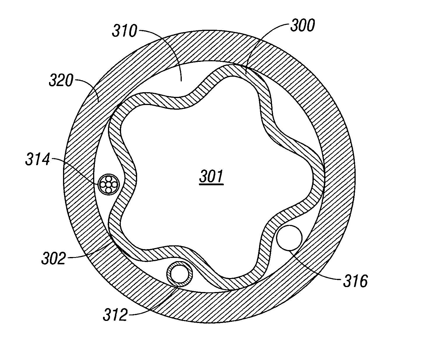
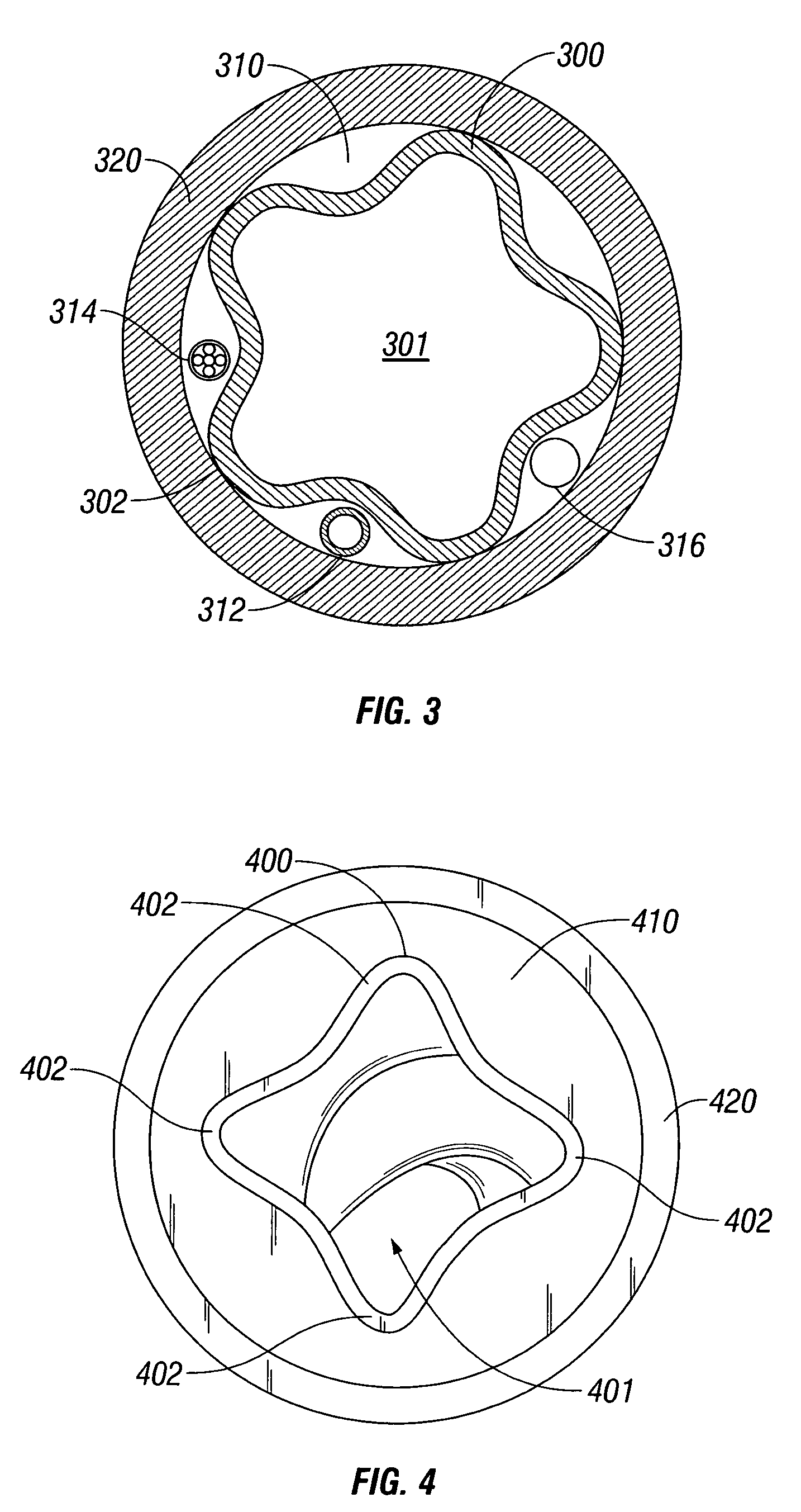
[0048]A stator used in a progressive cavity apparatus typically contains a resilient material layer in the profiled helical bore to aid in sealing the cavities formed between the rotor and stator. In a preferred embodiment, and as described below, the resilient material is an elastomer. However, one skilled in the art will readily appreciate that any resilient material can be used without departing from the spirit of the invention. A resilient material can be homogenous, composite, fiber reinforced, mesh reinforced, or formed from layers of different material, which can include at least one non-resilient layer. Preferably, the inner surface of a resilient material tube is resilient; however the outer surface of a resilient material tube can be resilient or even non-resilient and still be considered a resilient material tube as used herein. A profiled helical tube can be resilient to a cylindrical shape, for example, if the profiled helical resilient material tube is formed by confor...


PUM

PropertyMeasurementUnit
Temperatureaaaaaaaaaa
thicknessaaaaaaaaaa
resilientaaaaaaaaaa

Abstract

The present invention relates to a resilient material lined stator and method of forming. A method of forming a resilient material lined stator can include disposing a resilient material tube 400 with a profiled helical inner surface 401 into the bore of a body 420. A cast material 410 can be disposed therebetween. The cast material 410 can bond to the body 420 to form a resilient material lined stator or the body 420 can be removed. The cast material 310 can include a conduit 312 or conductor 314 extending therethrough. The cast material 310 can include a pathway 316 formed therethrough. The resilient material can be an elastomer.

Description

BACKGROUND[0001]The invention relates generally to stators for use with progressive cavity pumps or motors. More specifically, to a resilient material lined stator and a method of forming the stator.[0002]Progressive cavity pumps or motors, also referred to as a progressing cavity pumps or motors, typically include a power section consisting of a rotor with a profiled helical outer surface disposed within a stator with a profiled helical inner surface. The rotor and stator of a progressive cavity apparatus operate according to the Moineau principle, originally disclosed in U.S. Pat. No. 1,892,217.[0003]In use as a pump, relative rotation is provided between the stator and rotor by any means known in the art, and a portion of the profiled helical outer surface of the rotor engages the profiled helical inner surface of the stator to form a sealed chamber or cavity. As the rotor turns eccentrically within the stator, the cavity progresses axially to move any fluid present in the cavity...

Claims


Application Information

Patent Timeline
Patent Type & Authority Patents(United States)
IPC IPC(8): B23P15/00F01C5/00
CPCF04C2/1075Y10T29/49242B29C39/10B29C39/123B29C39/126B29C70/681B29C70/78B29C70/84H02K15/02H02K15/10
Inventor LEE, LAWRENCESHEPHERD, MICHAEL
Owner SCHLUMBERGER TECH CORP
Why Eureka
Try Eureka