Fence assembly and related methods

a technology of modular fences and assembly methods, applied in the field of modular fence systems, can solve the problems of exacerbated handling and storage problems, high labor intensity, and high labor intensity, and achieve the effects of reducing the overall cost of the system, reducing labor intensity, and reducing labor intensity

Active Publication Date: 2010-06-22
LARSEN CHARLES
View PDF27 Cites 13 Cited by
  • Summary
  • Abstract
  • Description
  • Claims
  • Application Information

AI Technical Summary

Benefits of technology

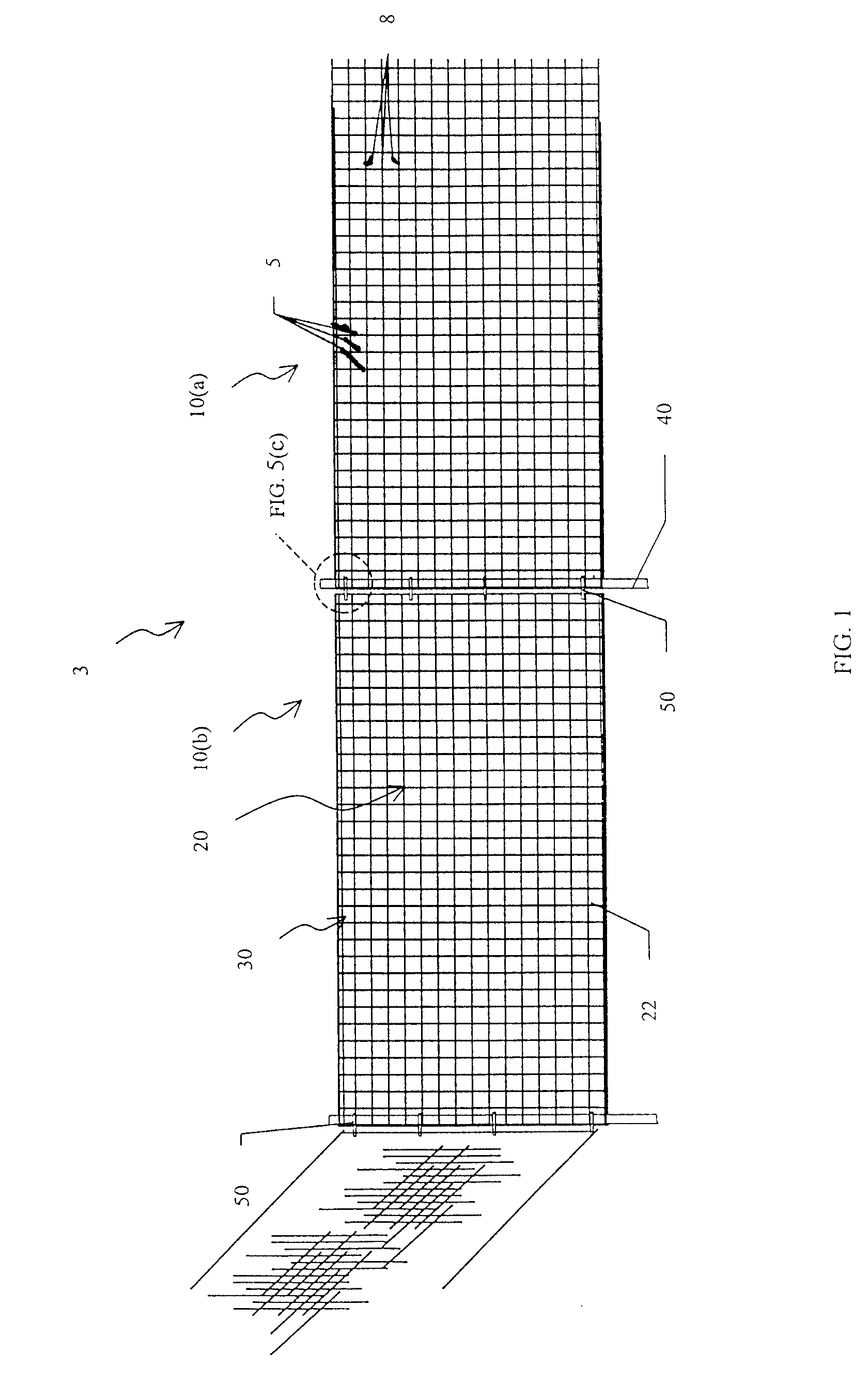
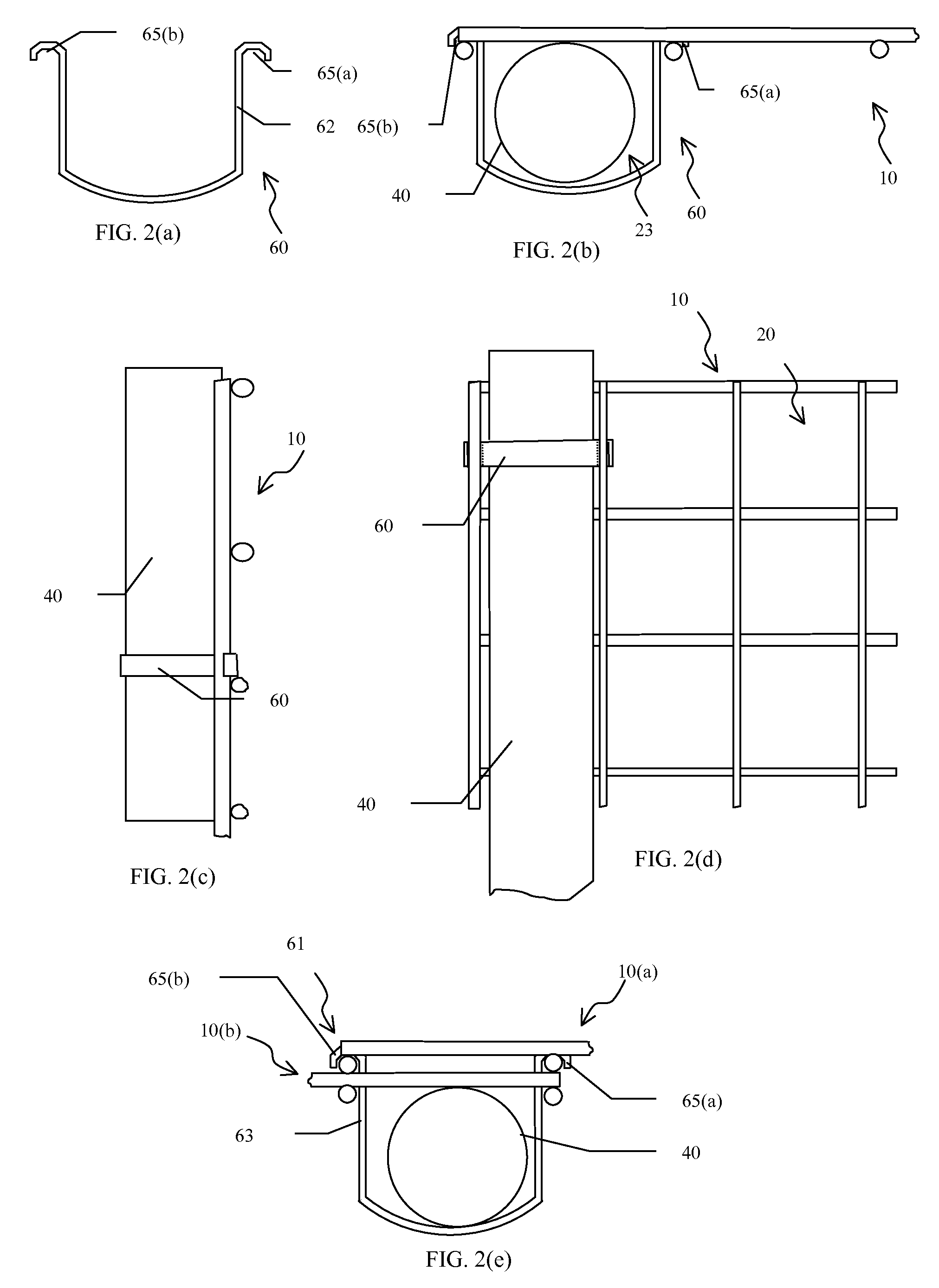
[0009]One embodiment of the invention describes a fence assembly that preferably uses known welded wire mesh panels, a standard post, and a retaining element or bracket that provides for simple attachment of the assembly at the time of installation without the use of bolt-on clamping style brackets. The brackets of the present invention affix the mesh to the post in a fashion that provides for vertical structural rigidity without the use of a separate vertical framing member or members, resulting in significant material savings. Preferably, this same bracket can be connect one or more adjacent panels without the use of a separate framing member or additional post. Furthermore, this embodiment of the fence assembly of the invention affords relatively broad tolerances that allow for efficient installation under a variety of circumstances.
[0010]A wide variety of embodiments of the invention enable a fixed attachment of one or more panels to one or more posts, without the use of labor intensive bolt-on clamping brackets. This fixed attachment permits lighter gauge wire to be used in the mesh, lowering the overall cost of the system.
[0011]Certain embodiments allow the post or posts to serve a dual purpose, thereby eliminating the need for separate vertical framing members or for permanently attached mounting rings on the panel. As a consequence, and among other things, handling and storage are made more efficient, a significant material savings is realized, and labor to assemble the panels is substantially reduced.

Problems solved by technology

While these panels have several advantages as previously mentioned, their bulkiness typically creates a handling and storage problem that is significant, particularly when one considers the number of times these reusable fence sections are handled, stored, reused, etc.
Arguably, this kind of connection may be more secure, however, the time necessary to bolt the panels to the post make the assembly and disassembly process relatively time consuming.
In addition, although the typically large attachment rings on the framework of these panels are efficient for installation purposes, those large rings exacerbate the problems of handling and storage, such as by spacing the panels from each other when stacked in storage.
Although theoretically these panels of welded wire mesh with horizontal stiffening bends and / or horizontal framing members may be fixed directly to the posts by a bolted clamping bracket or similar means, the additional labor for installing these clamps and the requisite precision in spacing the posts has not made this a viable option for temporary fence applications.

Method used


Image

  • Fence assembly and related methods
  • Fence assembly and related methods
  • Fence assembly and related methods

Examples


embodiment 50

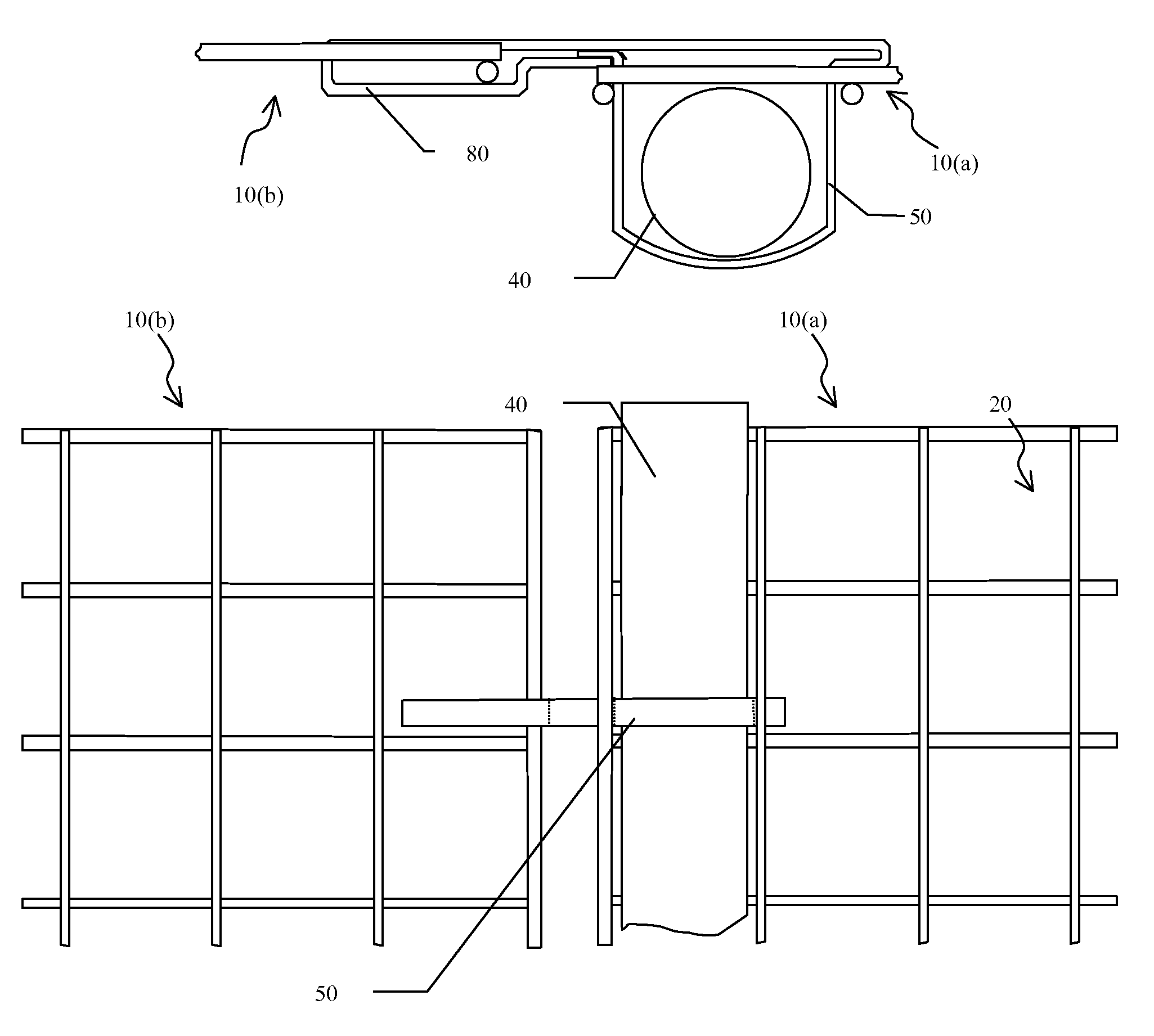
[0063]FIG. 3(b) illustrates yet another bracket embodiment 50 of the system. Similar to the housing used in FIG. 3(a), bracket 50 incorporates an engagement housing 80 to secure the adjacent panel. However, instead of the open style pocket 23 used in FIG. 3(a), the bracket of FIG. 3(b) utilizes a closed style pocket 24. Therefore, although the housing 80 is formed along one side of the bracket in FIG. 3(a), the housing 80 is connected to the opposite side of the bracket in FIG. 3(b) via a strip of metal along the top of the bracket which forms the closed style pocket 24. The bracket 50 is preferably installed by flexing the housing 80 around a spaced apart wire of one of the panels 10. The closed style pocket 24 is then preferably inserted, pushed, or similarly positioned through the spaced apart wires of the other panel 10 to provide a receiving pocket 24 for the post 40 that secures the post 40 to the panel 10.

[0064]A tab 55 or similarly formed element of the bracket 50 can be pro...

embodiment 150

[0067]FIG. 6(a) is a perspective view of another bracket embodiment 150 which further adds cut out areas 160(a), 160(b) within the wall of the bracket 150 permitting the bracket 150 to be installed around one of the horizontal wires 161 of each of the panels, which can further restrict the movement of the bracket 150 and therefore movement of the panels within the structure. In this embodiment, the bracket 150 includes a first pocket 17 and a second pocket 18 configured to receive the vertical post 40. The first and second pockets 17, 18 are spaced apart from each other and formed along the same side of the bracket 150. The first and second pockets 17, 18 are formed at least in part by a first pair and second pair of generally parallel sides, respectively. The sides are connected to the engagement surfaces 65(a1), 65(b1) and spaced apart from each other. The bracket 150 also includes a first housing 31 and a second housing 32 spaced apart from each other and formed along the other s...


PUM


Abstract

Fence apparatus and related methods for making a fence panel and for connecting the panel to other panels and post elements to form a modular type fence are disclosed. These include a generally planar section of fencing material formed from spaced-apart wires, and the related brackets and posts of the system providing simplified installation, removal, handling, and storage of the fence components.

Description

FIELD OF THE INVENTION[0001]The present invention relates to a modular type fence system, and apparatus and methods for assembling components of the system. It preferably includes one or more retaining elements for assembling one or more fence panels and associated posts, and provides for (among other things) improved strength-to-weight characteristics, ease of installation and removal, and efficient handling and storage of the components and the fence system.INCORPORATION BY REFERENCE[0002]The contents of each U.S. patent or other reference, if any, cited in this application, are hereby incorporated by reference.BACKGROUND[0003]Temporary fence is increasingly becoming a fixture around construction sites and special events for safety, security, crowd control, or simply to restrict access. Temporary fences are constructed in numerous ways and from a variety of materials. Most commonly these barriers are constructed of posts driven into the ground, with rolled chain link mesh or plast...

Claims


Application Information

Patent Timeline
Patent Type & Authority Patents(United States)
IPC IPC(8): E04H17/04E04H17/14E04H17/16
CPCE04H17/163E04H17/161
Inventor LARSEN, CHARLES
Owner LARSEN CHARLES
Why Eureka
Try Eureka