
Sprocket tooth profile for a roller or bush chain

a technology of bush chain and sprocket, which is applied in the direction of gearing, gearing elements, hoisting equipment, etc., can solve the problems of significant noise sources, limited design to a unidirectional roller chain drive, and long-known noise generated by the meshing of the bush chain with the sprocket, so as to prevent the radial impact of the root of the tooth during engagemen

Inactive Publication Date: 2010-06-22
BORGWARNER INC
View PDF30 Cites 10 Cited by
  • Summary
  • Abstract
  • Description
  • Claims
  • Application Information

AI Technical Summary

Benefits of technology

The patent describes an improved sprocket design that reduces damage to the teeth during engagement with a roller or bush chain. The sprocket has a smooth profile that prevents radial impact with the root of the tooth. The teeth on the sprocket have a root radius that matches that of the chain, and the center point of the root radius is located inside the sprocket's pitch circle. This design allows the chain's rollers or bushings to impact the sprocket teeth in a way that reduces damage to the teeth. This invention can be used with both roller and bush chains.

Problems solved by technology

Noise generated by a roller chain meshing with a sprocket is a long recognized problem.
One of the most significant sources of noise in a typical roller chain drive results from the repeated impacts between the rollers and the sprockets as the rollers seat between the teeth of the sprocket.
However, this design is limited to a unidirectional roller chain drive because of the asymmetry of the tooth profile as generally shown by FIG. 13.

Method used


Image

  • Sprocket tooth profile for a roller or bush chain
  • Sprocket tooth profile for a roller or bush chain
  • Sprocket tooth profile for a roller or bush chain

Examples


Embodiment Construction

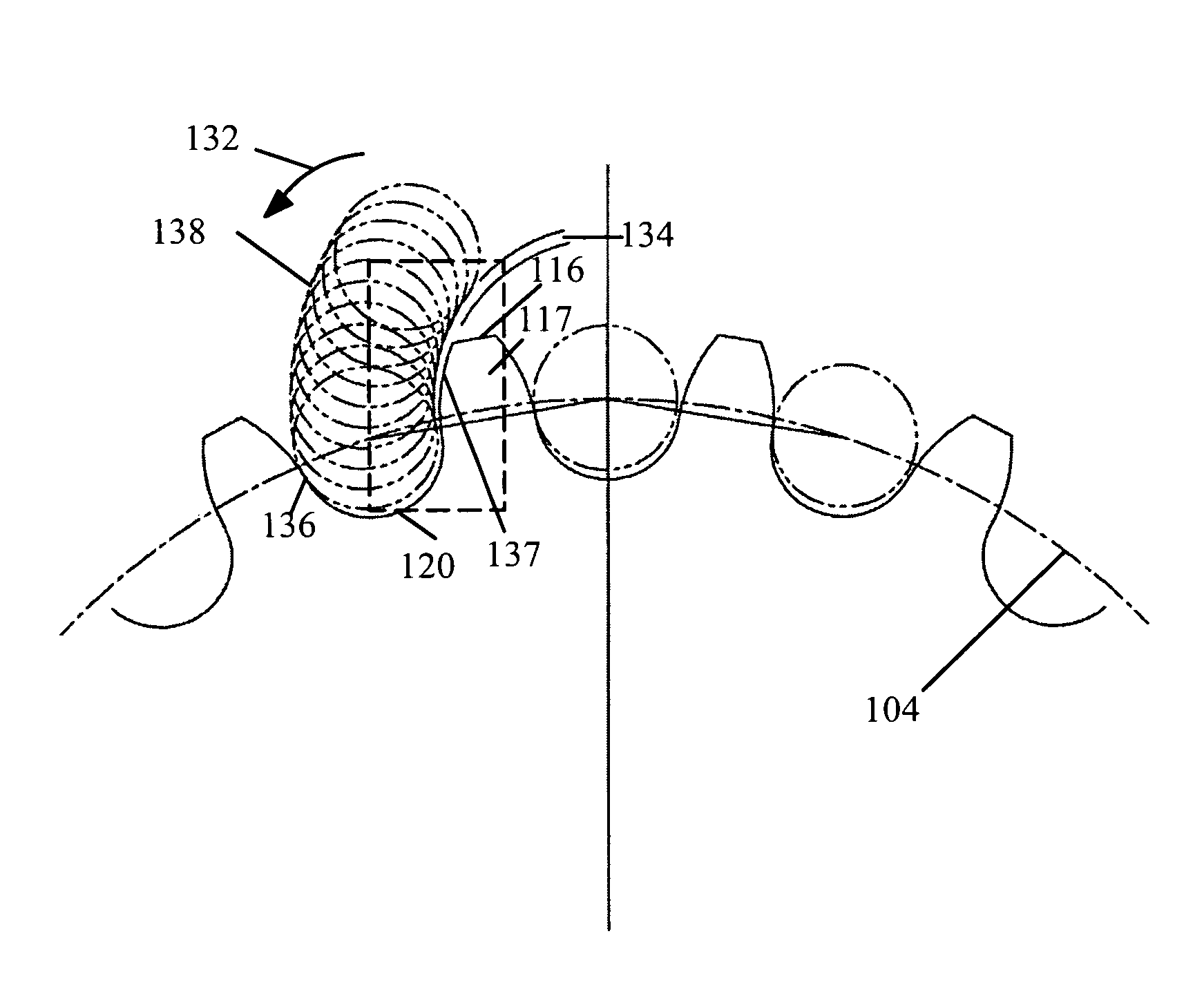
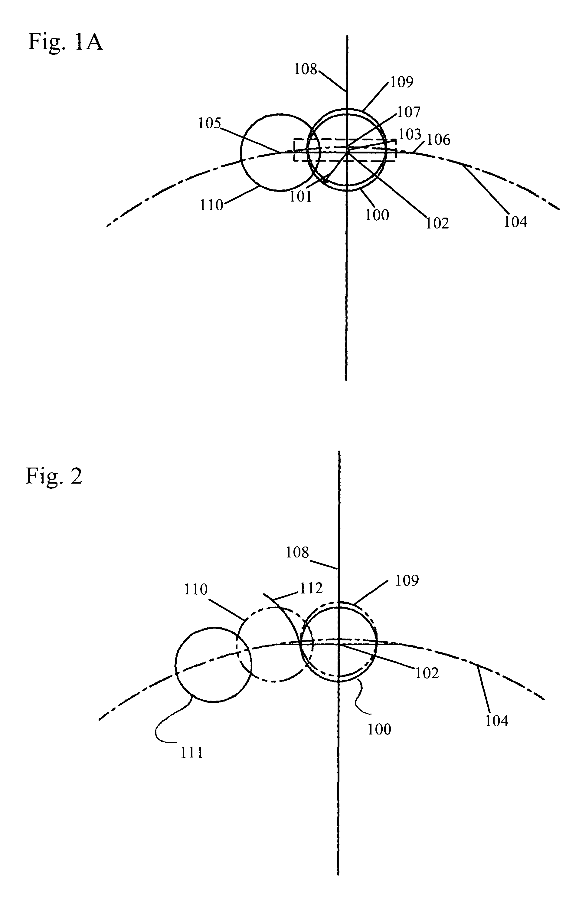
[0030]The present invention alters the contact between the sprocket teeth and the roller or bush chain by providing teeth with a root radius equivalent to that of the chain engaging component, with the center point of the root radius located one chordal distance inside the sprocket pitch circle. The present invention uses the standard root radius from ISO, but, unlike the prior art, the root radius is located one chordal distance inside the pitch circle. The present invention decreases noise and backlash.

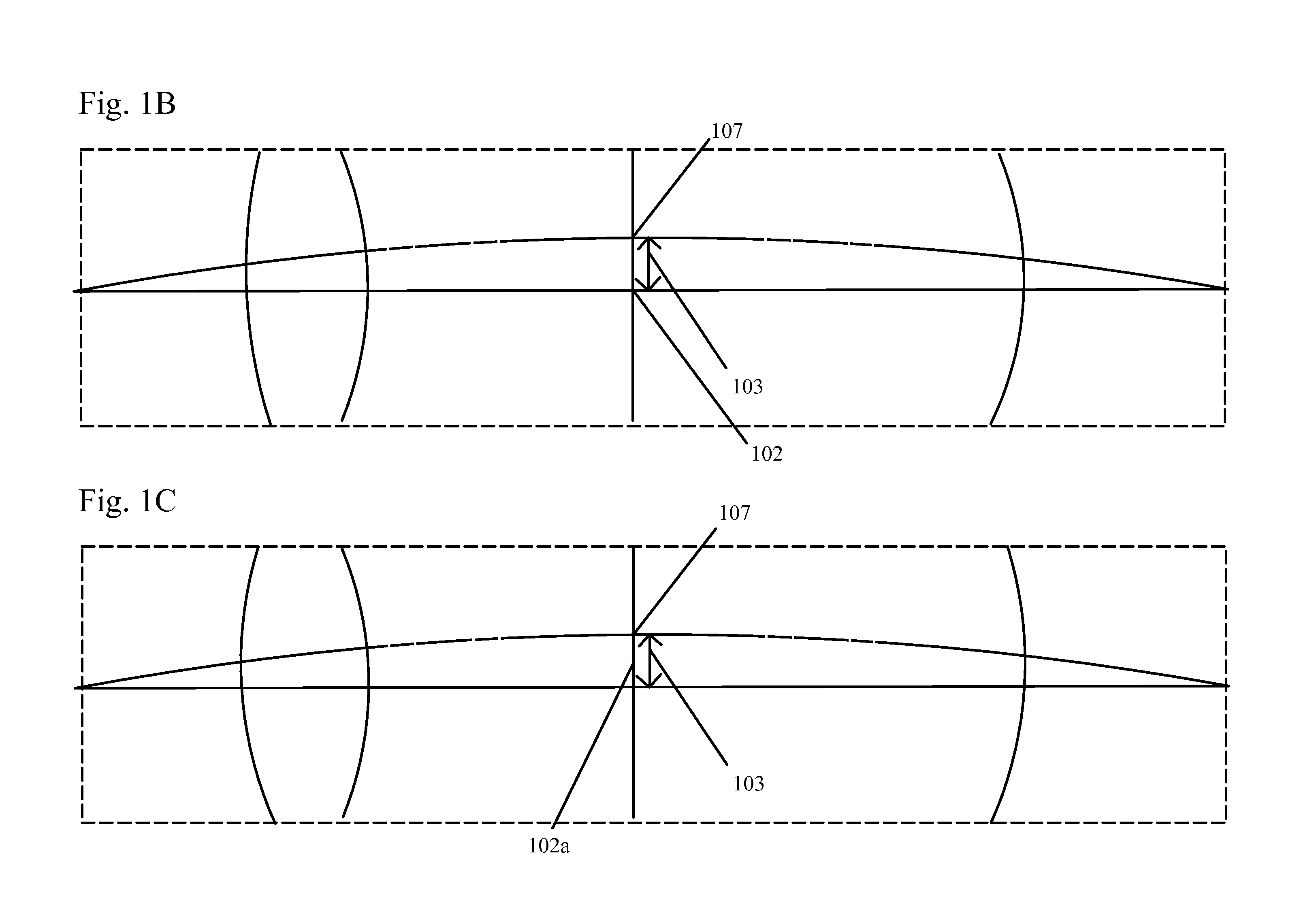
[0031]Chordal distance (also known as chordal rise and fall) is defined as the difference between the distance from the center of the sprocket to the centerline of the chain that is perpendicular to the centerline of the sprocket when a chain roller member (for a roller chain) or a chain bushing member (for a bush chain) is on the sprocket centerline and the distance when two roller members or two bushing members are equally spaced about the sprocket centerline. This value, or radia...


PUM


Abstract

An improved sprocket profile for engaging a roller or bush chain smoothly and preventing radial impact with the root of the tooth during engagement. Contact between the sprocket teeth and the roller chain is altered by providing teeth with a root radius equivalent to that of the chain engaging component, with the center point of the root radius located one chordal distance inside the sprocket's pitch circle. This profile allows chain rollers or bushings to impact sprocket teeth tangentially on their flanks rather than radially on their tooth root.

Description

BACKGROUND OF THE INVENTION[0001]1. Field of the Invention[0002]The invention pertains to the field of sprockets for roller or bush chains. More particularly, the invention pertains to a sprocket that reduces the noise generated when the roller or bush chain and the sprocket mesh.[0003]2. Description of Related Art[0004]Conventional chain sprocket interfaces seat the roller or bush in the root of the sprocket tooth as if the sprocket is held stationary and a taut chain is wrapped around it. A roller swinging-on an arc the length of a chain pitch around the center of the previous roller, located on the pitch circle of the sprocket, contacts the root of the sprocket tooth when reaching the pitch circle of the sprocket.[0005]FIG. 11 shows a chain C having rollers R engaging sprockets S1 and S2. Noise generated by a roller chain meshing with a sprocket is a long recognized problem. One of the most significant sources of noise in a typical roller chain drive results from the repeated imp...

Claims


Application Information

Patent Timeline
Patent Type & Authority Patents(United States)
IPC IPC(8): F16H7/06F16H55/30
CPCF16H7/06F16H55/30F16H2055/306
Inventor MARKLEY, GEORGE L.
Owner BORGWARNER INC
Learn More