Time-lapsed diffusivity logging for monitoring enhanced oil recovery

a technology of enhanced oil recovery and diffusivity logging, which is applied in the field of time-lapsed diffusivity logging for monitoring enhanced oil recovery, can solve the problems of ineffective current reservoir monitoring techniques that measure the changes in water saturation to calculate the displacement of oil, ineffective induction tools that measure conductivity or pulsed neutron tools that measure carbon/oxygen ratio, and ineffective thermal neutron-emitting tools that measure conductivity

Inactive Publication Date: 2010-06-22
SCHLUMBERGER TECH CORP
View PDF9 Cites 36 Cited by
  • Summary
  • Abstract
  • Description
  • Claims
  • Application Information

AI Technical Summary

Problems solved by technology

Specifically, when the reservoir is injected with gas in a “miscible gas flood” operation, recovered oil is not predominately replaced by formation water, and therefore current reservoir monitoring techniques that measure the changes in water saturation to calculate the displacement of oil will be ineffective.
For example, thermal neutron-emitting tools that measure changes in capture cross section, induction tools that measure conductivity or pulsed neutron tools that measure carbon / oxygen ratio are ineffective when the water saturation level does not appreciably change.
However, reliance upon changes in HI loses effectiveness if there is little difference in density and HI between the oil and gas.
However, NMR tools are not being used during completion, production and monitoring of wells because typical metallic completion hardware attenuates the pulsed radio frequency signals used during NMR imaging.
Further, in a cased hole, an NMR tool would be ineffective in measuring diffusivity if the cement bond between the casing and formation is poor and / or fluid is disposed in the annulus between the casing and formation.
Specifically, a poor cement bond between the casing and formation results in areas of the annulus where voids in the cement are present.

Method used


Image

  • Time-lapsed diffusivity logging for monitoring enhanced oil recovery
  • Time-lapsed diffusivity logging for monitoring enhanced oil recovery
  • Time-lapsed diffusivity logging for monitoring enhanced oil recovery

Examples


Embodiment Construction

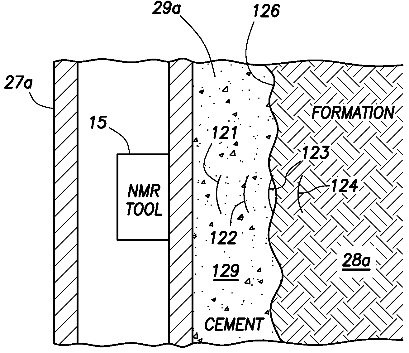
[0027]The use of nuclear magnetic resonance (NMR) imaging behind eccentered, non-conventional casing for measuring diffusivity and changes in various fluid saturations is disclosed. The casing should be non-conductive and non-magnetic and therefore preferably non-metallic. NMR tools are normally designed to run in open holes and not cased holes because the conventional steel casing used in a cased hole is conductive and strongly attenuates the pulsed radio frequency used in NMR measurements. Currently the non-conventional casings made of fiberglass and / or reinforced epoxy or other resins are used in wells where there is an issue of corrosion from CO2, H2S and formation brine. The combined use of NMR and a decentralized, non-magnetic and non-conductive casing will allow investigation beyond the annulus.

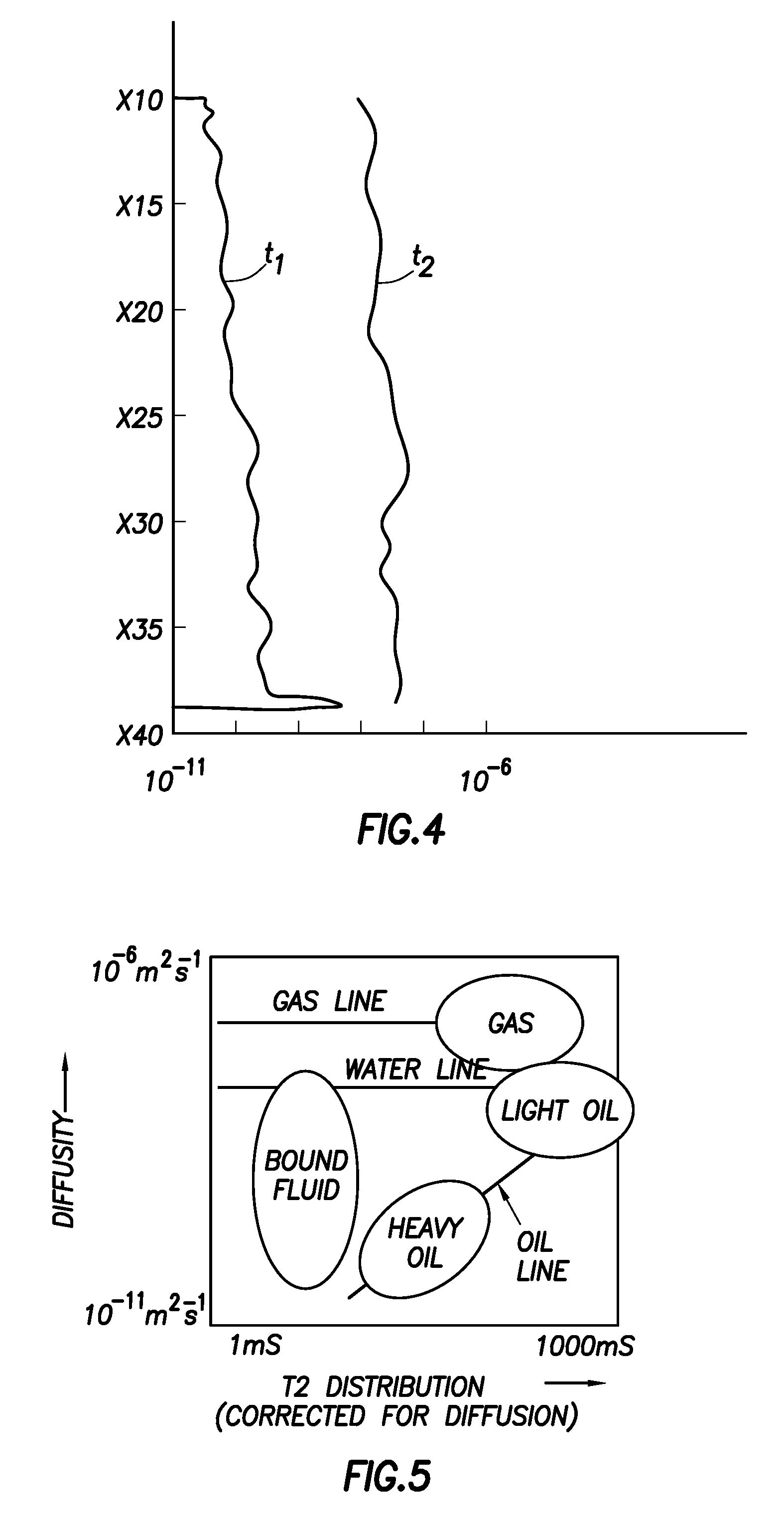
[0028]Nuclear magnetic resonance (NMR) tools measure both diffusivity and HI. Therefore, for the reasons set forth above, in certain circumstances and particularly when evaluating a re...


PUM


Abstract

The use of time-lapsed NMR diffusivity measurements in an observation well is disclosed. The observation well is cased in the zone of interest with non-magnetic and non-conductive casing that is invisible to the NMR tool. Second, because NMR measurements have a dead zone in front of the antenna depending on the spatial variation of the fixed magnet strength, for example about 2.7 inches, a distance between the casing and the formation is reduced to less than the dead zone length by drilling the observation well at small deviation of about 5° and running the casing without centralizers. Both the casing and the pad-type NMR tool will follow the low side of the borehole, ensuring the measurement volume of the NMR tool is inside the formation and beyond the annulus. With the appropriate observation well completion, time-lapse diffusivity measurements with pad-type NMR tools can address several shortcomings in the current practice of monitoring EOR processes that rely upon changes in density and hydrogen index (HI). Various uses of NMR imaging in wells cased with non-metallic casing are also disclosed.

Description

BACKGROUND[0001]1. Technical Field[0002]New techniques are disclosed that employ nuclear magnetic resonance (NMR) logging tools to measure time-lapse diffusivity in an observation well of a reservoir undergoing enhance oil recovery (EOR). More specifically, techniques are disclosed which eliminate problems associated with changes in fluid or poor cement bond in the annulus between the well casing the formation which render NMR logs ineffective. The techniques include drilling a deviated observation borehole and using non-magnetic, non-conductive casing without centralizers in the zone of interest thereby ensuring that the casing rests against the formation on the low side of the deviated borehole. The zone of interest is logged with an NMR tool with the pad directed radially at the portion of the casing that rests against the low side of the borehole ensuring that the shallowest zone of interest lies in the formation and not the annulus. Other cased-hole NMR imaging / logging techniqu...

Claims


Application Information

Patent Timeline
Patent Type & Authority Patents(United States)
IPC IPC(8): G01V3/00
CPCG01V3/32
Inventor EDWARDS, JOHNLADVA, HEMANT K. J.
Owner SCHLUMBERGER TECH CORP
Why Eureka
Try Eureka