Firearm adapted for use in low light, illuminating rear sight, and method for aligning sights in low light environments

a low-light environment and rear sight technology, applied in the direction of sighting devices, weapons, weapon components, etc., can solve the problems of difficult identification of targets and distinguishing targets from background or any other clutter in the field of view, and achieve the effect of simple and reliable sight system

Inactive Publication Date: 2010-06-29
KENG
View PDF4 Cites 62 Cited by
  • Summary
  • Abstract
  • Description
  • Claims
  • Application Information

AI Technical Summary

Benefits of technology

[0012]Accordingly, it is a primary object of the present invention to overcome the above mentioned difficulties by providing a pistol or other firearm with a simple and reliable sight system adapted for use in low light or at night.
[0013]Another object of the present invention is providing an optical alignment device permitting a clear sight picture in low light or at night.
[0017]In use, a front blade or front post also containing a tritium insert is aligned within the rear sight's U-shaped array of illuminated segments, thereby providing an intuitive sight picture. Shooters are readily trained to use the firearm of the present invention when shooting in low light and in accordance with the method of the present invention, the shooter is simply instructed to “put the ball in the bucket” where the ball, in this instance, represents the front post's round illuminating tritium insert and the “bucket” represents the U-shaped array of illuminating tritium vials surrounding the rear sight notch.
[0019]The firearm of the present invention is particularly well suited for use in low light and is substantially safer in a firefight when compared to use of tactical flash lights in the like. When confronting a mobile armed subject, it may be undesirable to identify a user's location by attempting to illuminate the target with a flashlight. That flashlight essentially serves as a beacon and gives an armed opponent a target that is easy to find.
[0025]Preferably, dovetail projection's bottom surface includes a substantially ovoid transversely elongated indentation having a first substantially vertical closed end wall opposite a second substantially vertical end wall. The dovetail's indentation second end wall defines an open segment that provides access to the interior of the indentation from the side of the dovetail projection and the dovetail's indentation has a sidewall vertical extent (or depth) that substantially equals the thickness of the leaf spring biased locking member so that the leaf spring locking member can be forced against the dovetail bottom surface and completely into the dovetail indentation, so as to completely disengage the leaf spring biased locking member from the firearm receiver's transverse notch.

Problems solved by technology

Often, when shooting in low light, there are two difficulties.
First, it is difficult to identify the target and distinguish the target from the background or from any other clutter in the field of view.
Secondly, it is difficult when trying to keep the target in view to also properly align the sights in what is commonly referred to as an appropriate “sight picture.”

Method used


Image

  • Firearm adapted for use in low light, illuminating rear sight, and method for aligning sights in low light environments
  • Firearm adapted for use in low light, illuminating rear sight, and method for aligning sights in low light environments
  • Firearm adapted for use in low light, illuminating rear sight, and method for aligning sights in low light environments

Examples


Embodiment Construction

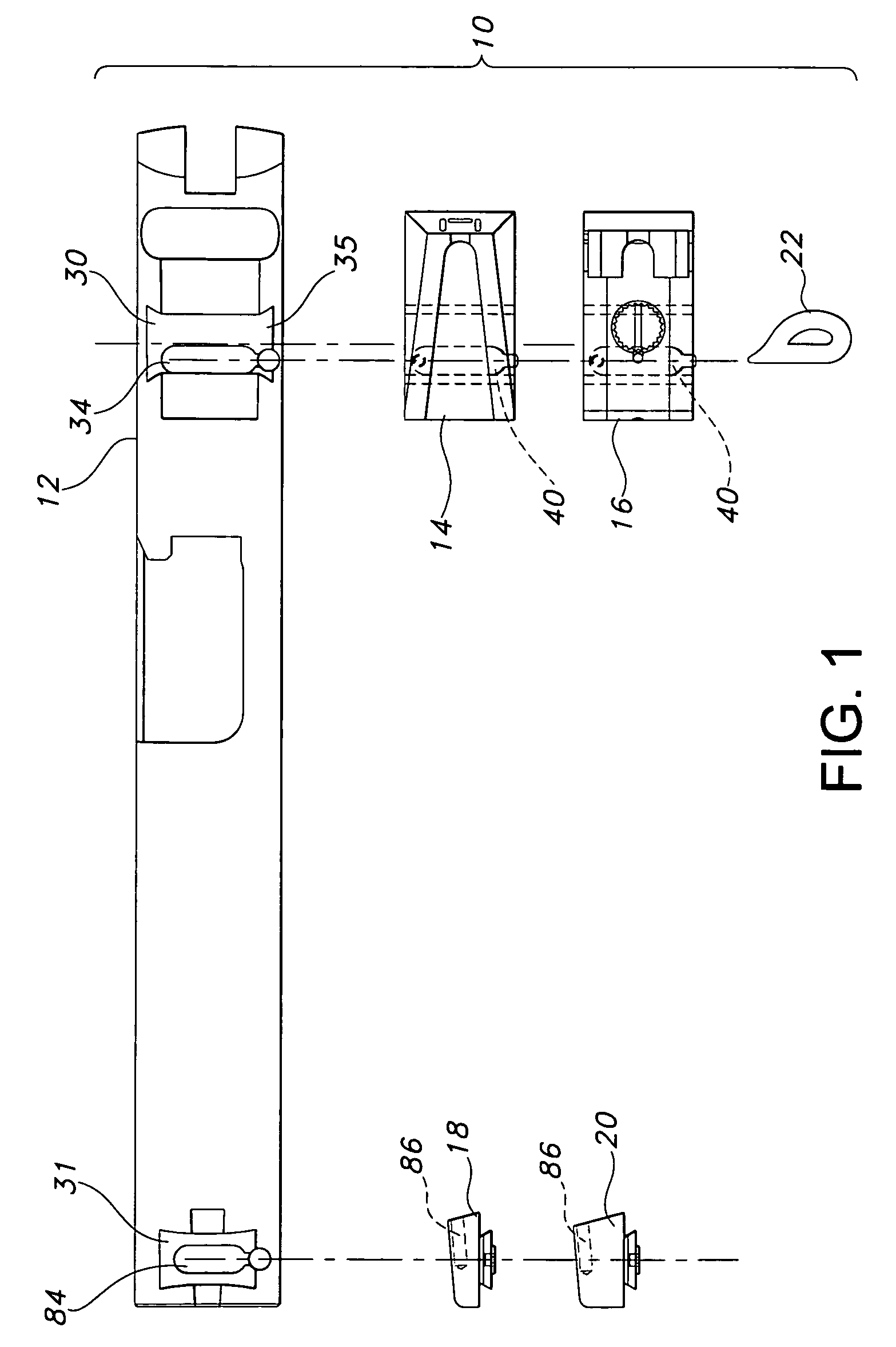
[0040]Referring now to FIGS. 1 through 8 of the accompanying drawings, the firearm and interchangeable sight system 10 of the present invention preferably includes a pistol slide or firearm receiver 12 having a transverse receiving notch 30. As above, “transverse” means in a left-right direction at a right angle to the pistol bore's central axis and lying in a horizontal plane when the pistol is held in a standard upright grip with the bore central axis in a horizontal plane.

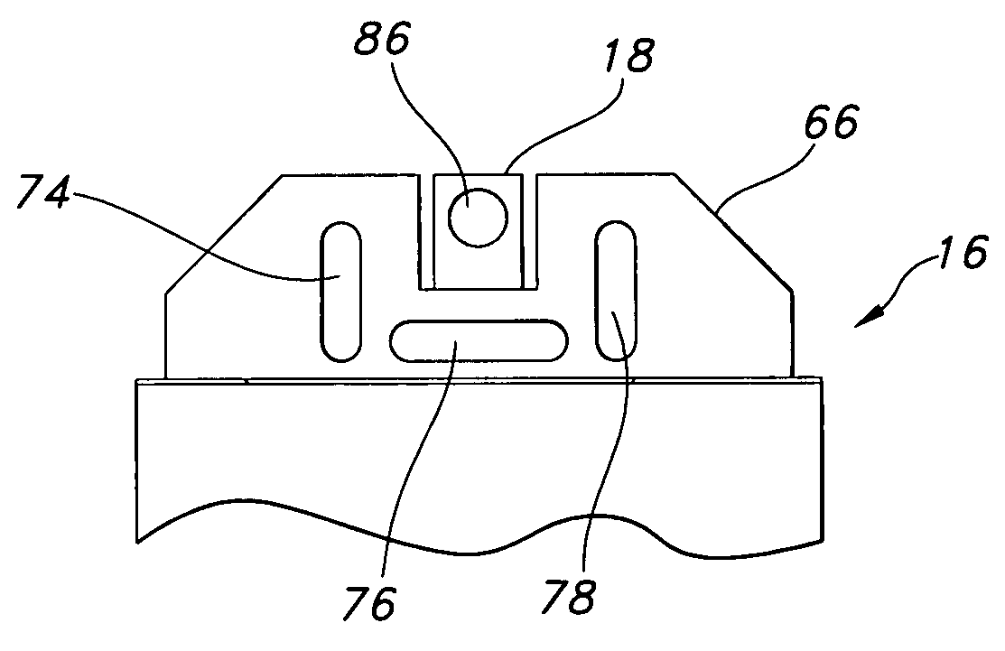
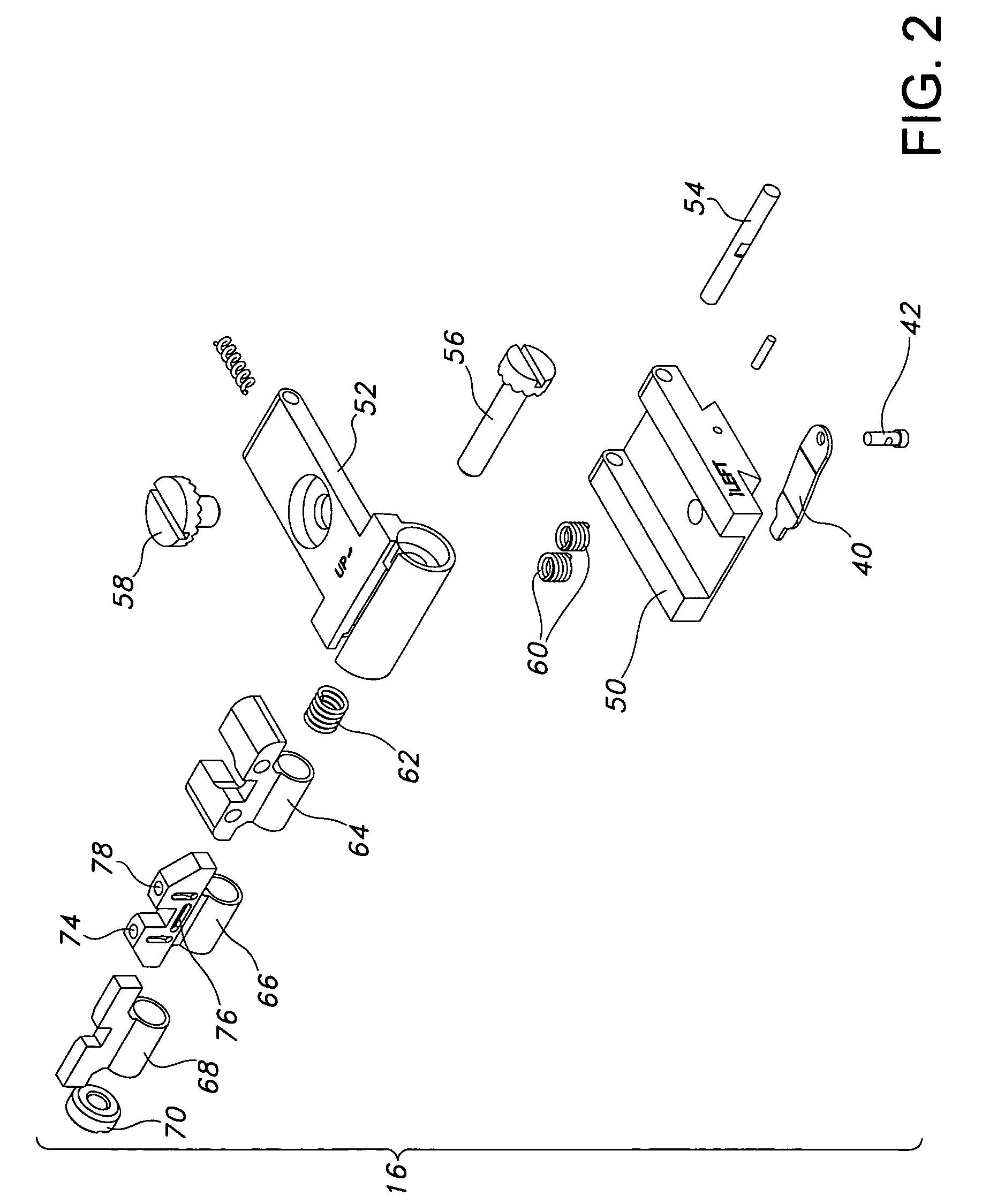
[0041]As best seen in FIG. 1, sight system 10 can be embodied as a kit including a plurality of rear sights (e.g., fixed rear sight 14 and adjustable rear sight 16) and a plurality of front sights (e.g., a short front blade 18 and a taller front blade 20), as well as a sight unlocking / removal tool 22.

[0042]Generally, the standardized dimensions for receiving notch 30 (as best seen in FIGS. 1, 4a and 4b) define a configuration adapted to accept a Novak-style dovetail-like sight projection 32 (best seen in FIGS. 3...


PUM


Abstract

A rugged adjustable, optical alignment system is well suited for use in low light environments or at night. A rear sight includes a U-shaped array of, preferably, first second and third substantially cylindrical, transparent, tritium vials arranged such that the elongated cylindrical side surfaces of the vials are exposed to define an array of elongated illuminated segments. The array is preferably in the shape of a “U” having a first horizontally aligned vial positioned below a sight notch with a second vertical vial positioned above and to the left of the notch. A third vertical vial is positioned to the right of the sighting notch, above the first vial. In use, a front blade or front post also containing a tritium insert is aligned within the rear sight's U-shaped array of illuminated segments, thereby providing an intuitive sight picture.

Description

RELATED PATENT APPLICATION AND PRIORITY CLAIM INFORMATION[0001]This application claims priority to co-pending provisional application number 60 / 647,402, filed Jan. 28, 2005, the entire disclosure of which is incorporated herein by reference.BACKGROUND OF THE INVENTION[0002]1. Field of the Invention[0003]The present invention relates to an optical alignment device such as a firearm sight adapted for use in low light and a method for mounting and adjusting optical devices such as gun sights on pistols or other firearms when operating in low light environments.[0004]2. Discussion of the Prior Art[0005]At present, a wide variety of optical sights are available for use on firearms such as handguns or pistols. A typical pistol has optical alignment fixtures or sights including a front sight and a rear sight that can be aligned with one another to form a sight picture for aligning the pistol's point of aim on the target. Prior art pistol sights are usually mounted along the top edge of the...

Claims


Application Information

Patent Timeline
Patent Type & Authority Patents(United States)
IPC IPC(8): F41G1/01
CPCF41G11/003F41G1/32
Inventor KENG, DA
Owner KENG
Why Eureka
Try Eureka