
Pallet jack with independently elevatable fork arms

a pallet jack and fork arm technology, applied in the direction of light-to-electrical conversion, loading/unloading vehicle arrangment, transportation items, etc., can solve the problems of likely tripping over and off-balance of loads while being transported, and achieve the effect of preventing tripping over

Active Publication Date: 2010-06-29
CLEARY TAMARA
View PDF14 Cites 57 Cited by
  • Summary
  • Abstract
  • Description
  • Claims
  • Application Information

AI Technical Summary

Benefits of technology

[0012]A pallet jack manual or electric is provided, including a pallet jack frame structure; a pallet jack wheel assembly secured to the pallet jack frame structure and including a pallet jack wheel rotatably mounted relative to the pallet jack frame structure; a first fork arm elevating mechanism secured to the pallet jack frame structure; a first fork arm operationally connected to the first fork arm elevating mechanism; a second fork arm elevating mechanism secured to the pallet jack frame structure and operable independent of the first fork arm elevating mechanism; a second fork arm operationally connected to the second fork arm elevating mechanism; so that each fork arm can move simultaneous, independent, in a straight forward, level manner, upwardly and downwardly, in unison of each other; so that the fork arm can life a pallet loaded with a stack of items which leans and is out of balance with one fork arm elevated higher than the other fork arm to compensate for the lean of the stack of items and thereby restore balance to the stack of items.
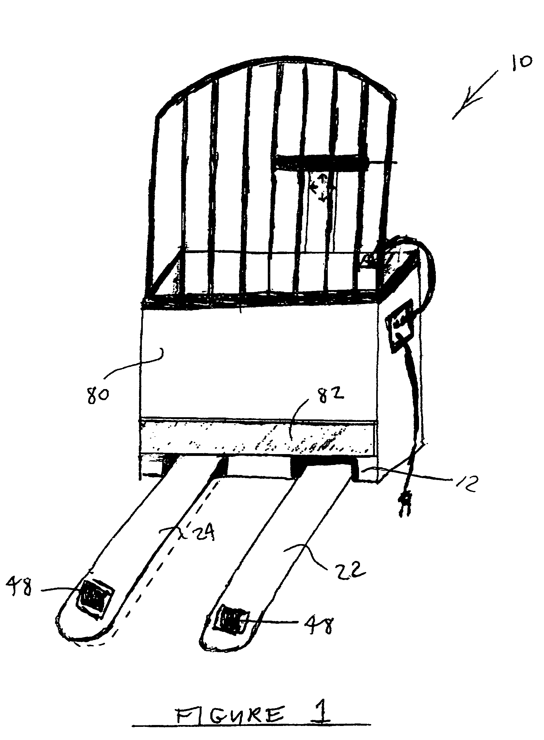
[0015]The frame structure preferably includes an upright load abutment wall extending upwardly from the pallet jack engaging fork arms. A opening in the abutment wall allows the fork arms to extend upwardly with out tilting the pallet jack, and for allowing a straight forward, level upwardly and downwardly movement in unison without tilting the pallet jack. A resilient shock absorbing load bumper preferably is provided on the wall forward face to prevent impact damage to the load and pallet jack, particularly during loading.

Problems solved by technology

A problem with operating these prior pallet jacks has been that item loads on pallets are often stacked off center and off balance so that if the pallet remains level as it is lifted, the loads remain off balance and are likely to tip over while being transported.

Method used


Image

  • Pallet jack with independently elevatable fork arms
  • Pallet jack with independently elevatable fork arms
  • Pallet jack with independently elevatable fork arms

Examples


Embodiment Construction

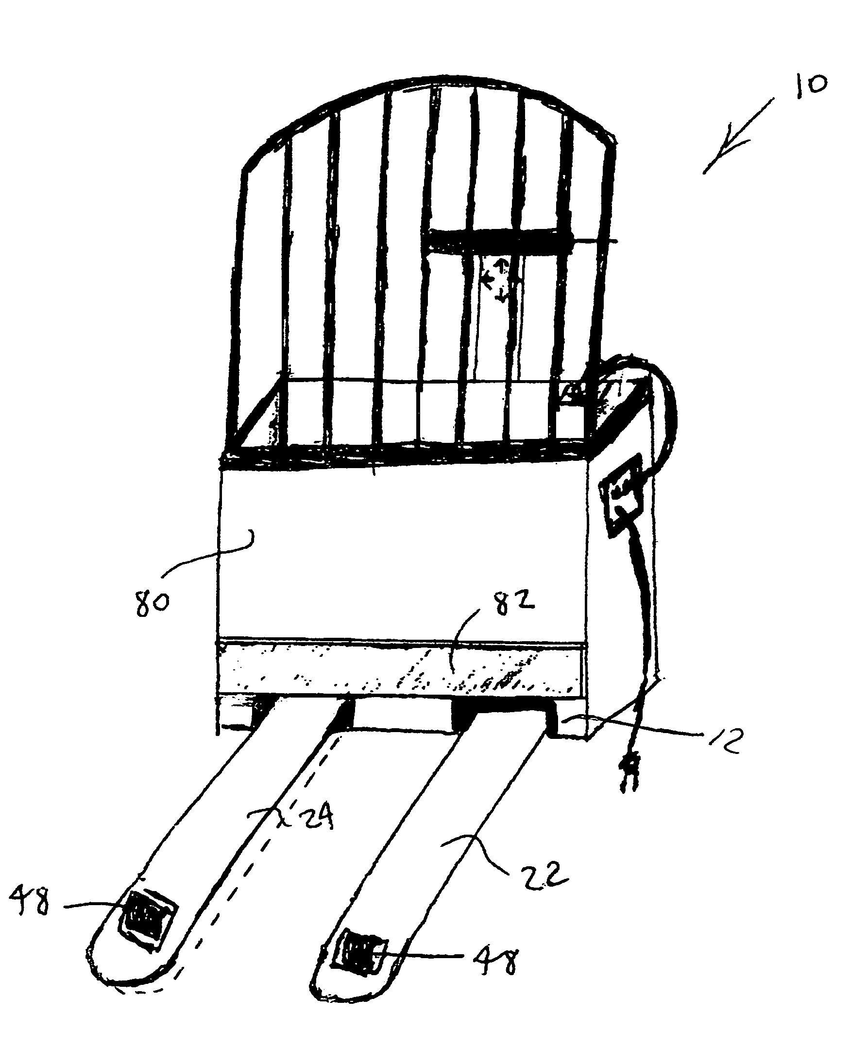
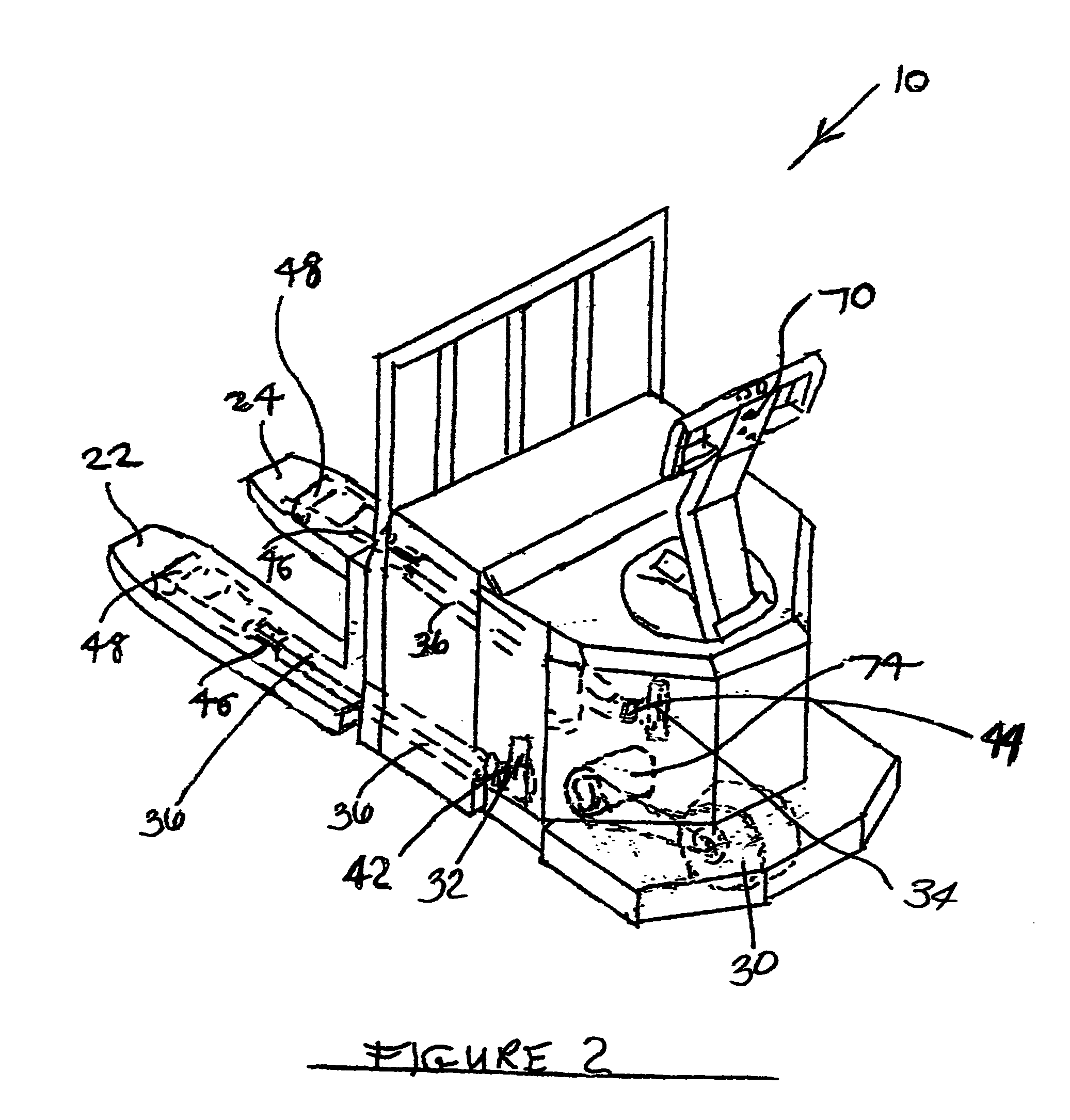
[0025]Referring to FIG. 1 number 10 being the pallet jack in whole, the frame structure 12 Preferably including an upright load abutment wall 80 extending upwardly from the pallet engaging fork arms 22 and 24. While also showing the independent fork arm 22 elevated in an upwardly position and fork arm 24 in a downwardly position by means of the riser wheel 48. A resilient shock absorbing load bumper 82 preferably is provided on wall 80 forward face to prevent impact damage to the load and pallet jack 10, particularly during loading. Referring to FIG. 2 The first and second fork arm 22 and 24 elevating means 32 and 34 preferably including first and second hydraulic piston and cylinder assemblies 32 and 34 drivable linked to first and second fork arm raisers 42 and 44. Each piston and cylinder assembly 32 and 34 moves the corresponding fork arm riser linkages 46 and fork arm 22 and 24 to lower fork arm wheels 48 simultaneously or independently to elevate the corresponding fork arm 22 ...


PUM


Abstract

A pallet jack with a pallet engaging fork having separate and independently movable first and second fork arms connected to independently controlled and operable first and second fork arm elevating means, for lifting a pallet loaded with a stack of items so that when the stack of items leans and is out of balance one fork arm can be elevated higher than the other to compensate and restore balance to the stack of items.

Description

FILING HISTORY[0001]This application continues from provisional application No. 60 / 509,554, filed on Oct. 8, 2003.BACKGROUND OF THE INVENTION[0002]1. Field of the Invention[0003]The present invention relates generally to the field of commercial trucks and carts for carrying merchandise items such as various types of product containers. More specifically the present invention relates to a pallet jack with a pallet engaging fork having separate and independently movable first and second fork arms connected to independently controlled and operable first and second fork arm elevating means, for lifting a pallet loaded with a stack of items so that when the stack of items leans and is out of balance one fork arm can be elevated higher than the other to compensate and restore balance to the stack of items. The fork arm elevating means may be powered electrically, manually or by any other suitable power source. The first and second fork arm elevating means preferably include first and seco...

Claims


Application Information

Patent Timeline
Patent Type & Authority Patents(United States)
IPC IPC(8): B66F9/12
CPCB60L1/003B60L8/003B66F9/065B66F9/12Y02T10/7083B60L2200/42B62B3/06B62B5/0009B62B2203/29Y02T10/7072
Inventor CLEARY, TAMARA
Owner CLEARY TAMARA
Learn More