Multi-color CMOS pixel sensor with shared row wiring and dual output lines

a pixel sensor and row wiring technology, applied in the field of multi-color cmos pixel sensors, can solve the problems of complicated problem, large number of wires, and complex problem, and achieve the effect of reducing the number of required wires through the pixel array and reducing the number of color select signals

Active Publication Date: 2010-06-29
FOVEON
View PDF41 Cites 12 Cited by
  • Summary
  • Abstract
  • Description
  • Claims
  • Application Information

AI Technical Summary

Benefits of technology

[0006]The present invention provides two different ways to reduce the number of required wires through the pixel array. The first adds another column output wire and reduces the number color enable, reset, and row enable signals. This embodiment adds another column wire and reduces the number of row signals from eight to four per row in the implementation described. The second embodiment also reduces the number of color select signals required by half, but does not add another column output signal.

Problems solved by technology

This type of pixel sensor has a unique challenge that the pixel needs lots of wires compared to a conventional CMOS pixel sensor because photodiodes are stacked increasing the number of photodiodes per unit area.
The number of wires are a problem because as the pixel sizes shrink there is less room for a large number of signal routing through the pixel array.
This problem is further complicated by the fact that certain wires need to move through the array in different directions and each metal layer is only useful for moving in one direction through the array unless the layer the wire is running on changes to other layers to avoid congestion.

Method used


Image

  • Multi-color CMOS pixel sensor with shared row wiring and dual output lines
  • Multi-color CMOS pixel sensor with shared row wiring and dual output lines
  • Multi-color CMOS pixel sensor with shared row wiring and dual output lines

Examples


Embodiment Construction

[0016]Persons of ordinary skill in the art will realize that the following description of the present invention is illustrative only and not in any way limiting. Other embodiments of the invention will readily suggest themselves to such skilled persons.

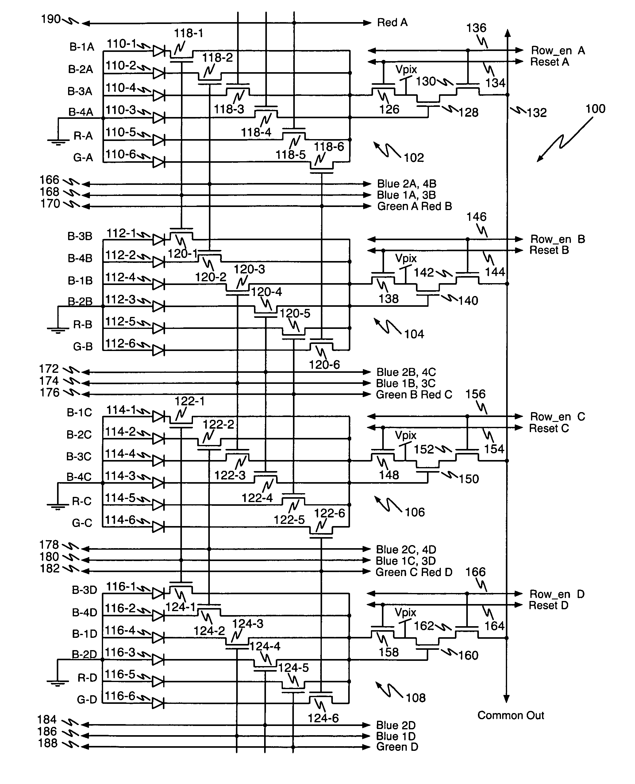
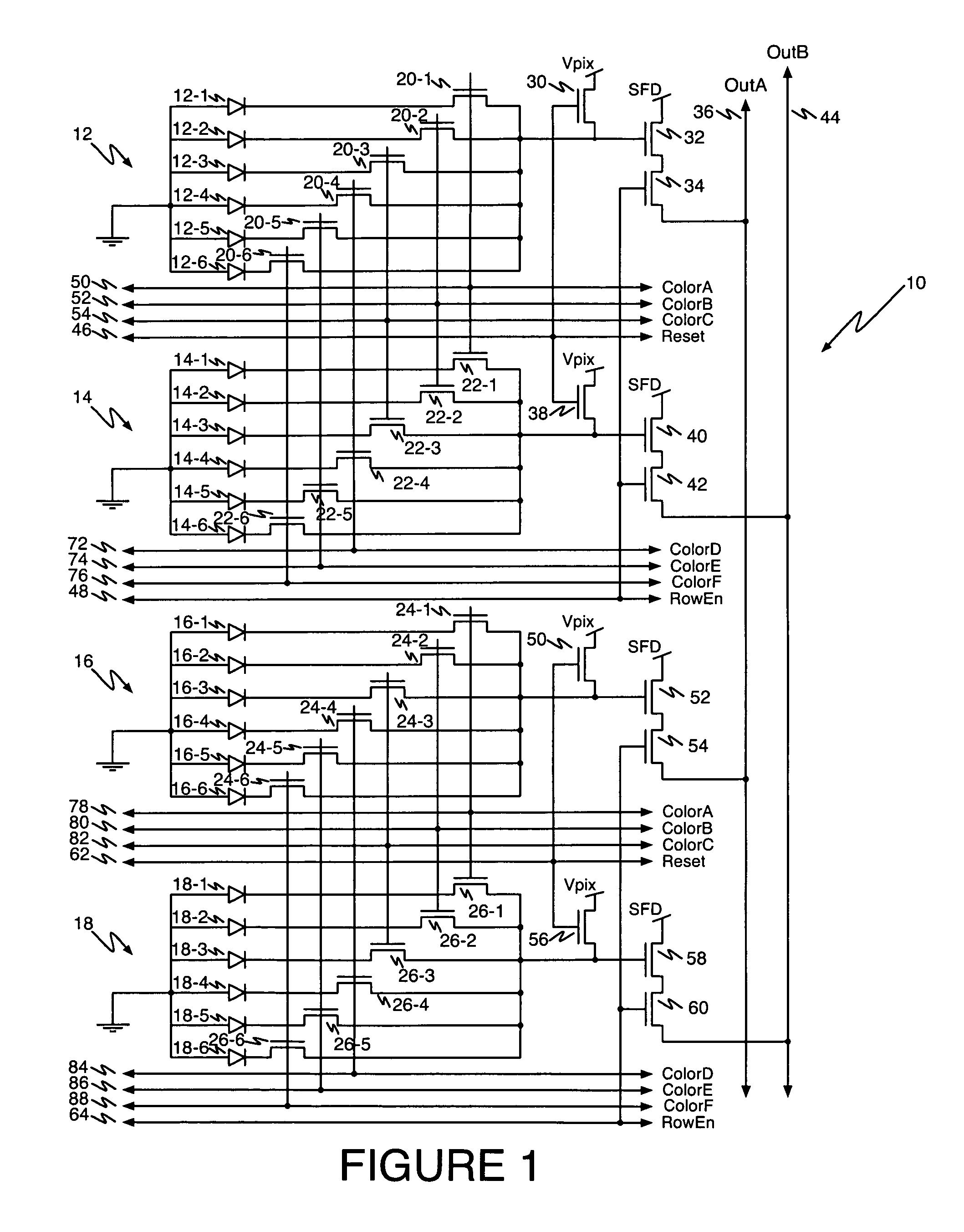
[0017]Referring first to FIG. 1, a schematic diagram shows a portion of an array 10 of multi-color CMOS pixel sensors according to the present invention comprising a part of a single column of the array containing four multi-color CMOS pixel sensors 12, 14, 16, and 18. Each pixel sensor includes six photodiodes identified in FIG. 1 at reference numerals 12-1 through 12-6, 14-1 through 14-6, 16-1 through 16-6, and 18-1 through 18-6. The anode of each photodiode is coupled to ground.

[0018]The cathode of each photodiode is separately coupled to a source / drain terminal of an n-channel select transistor to form a photocharge collection node. In pixel sensor 12, transistors 20-1 through 20-6 are the select transistors for photodiodes 12-1 t...


PUM


Abstract

An array of multicolor CMOS pixel sensors has a plurality of photosensors per pixel, each photosensor coupled to a single sense node through a select transistor having a select input, each pixel sensor including a reset transistor coupled to the sense node and having a reset input, an amplifier coupled to the sense node and a row-select transistor coupled to the amplifier. The select inputs and the reset inputs for pixel sensors in a pair of adjacent rows are coupled to select signal lines and reset signal lines associated with the pair of rows. The amplifier transistors in individual columns of each row are coupled to a column output line through a row-select transistor having a row-select input. The row-select inputs for pixel sensors in each row of the array are coupled to a row-select line associated with the row.

Description

BACKGROUND OF THE INVENTION[0001]1. Field of the Invention[0002]The present invention relates to multi-color CMOS pixel sensors. More particularly, the present invention relates to multi-color CMOS pixel sensors with shared row wiring and dual output lines.[0003]2. The Prior Art[0004]Multi-color CMOS pixel sensors are known in the art. Such pixel sensors are often configured with more than one photodiode per color. This type of pixel sensor has a unique challenge that the pixel needs lots of wires compared to a conventional CMOS pixel sensor because photodiodes are stacked increasing the number of photodiodes per unit area. The number of wires are a problem because as the pixel sizes shrink there is less room for a large number of signal routing through the pixel array. There also is a trend to using fewer layers of metal as the pixels get smaller to improve the optical stack between the microlens to the photodiodes. This problem is further complicated by the fact that certain wires...

Claims


Application Information

Patent Timeline
Patent Type & Authority Patents(United States)
IPC IPC(8): H01L27/00H01J40/14
CPCH04N5/3741H01L27/14641H04N5/37457H04N9/045H04N5/37452H01L27/14603H04N25/766H04N25/778H04N25/771H04N25/70H04N23/84
Inventor MERRILL, RICHARD B.
Owner FOVEON
Why Eureka
Try Eureka