
Impedance measurement using line-to-line current injection

a technology of current injection and impedance measurement, which is applied in the direction of impedence measurement, resistance/reactance/impedence, instruments, etc., can solve the problems of negative impedance, affecting the stability of the overall power system, prior current injection techniques of three-phase ac circuits,

Active Publication Date: 2010-06-29
UNIVERSITY OF MISSOURI +1
View PDF5 Cites 2 Cited by
  • Summary
  • Abstract
  • Description
  • Claims
  • Application Information

AI Technical Summary

Benefits of technology

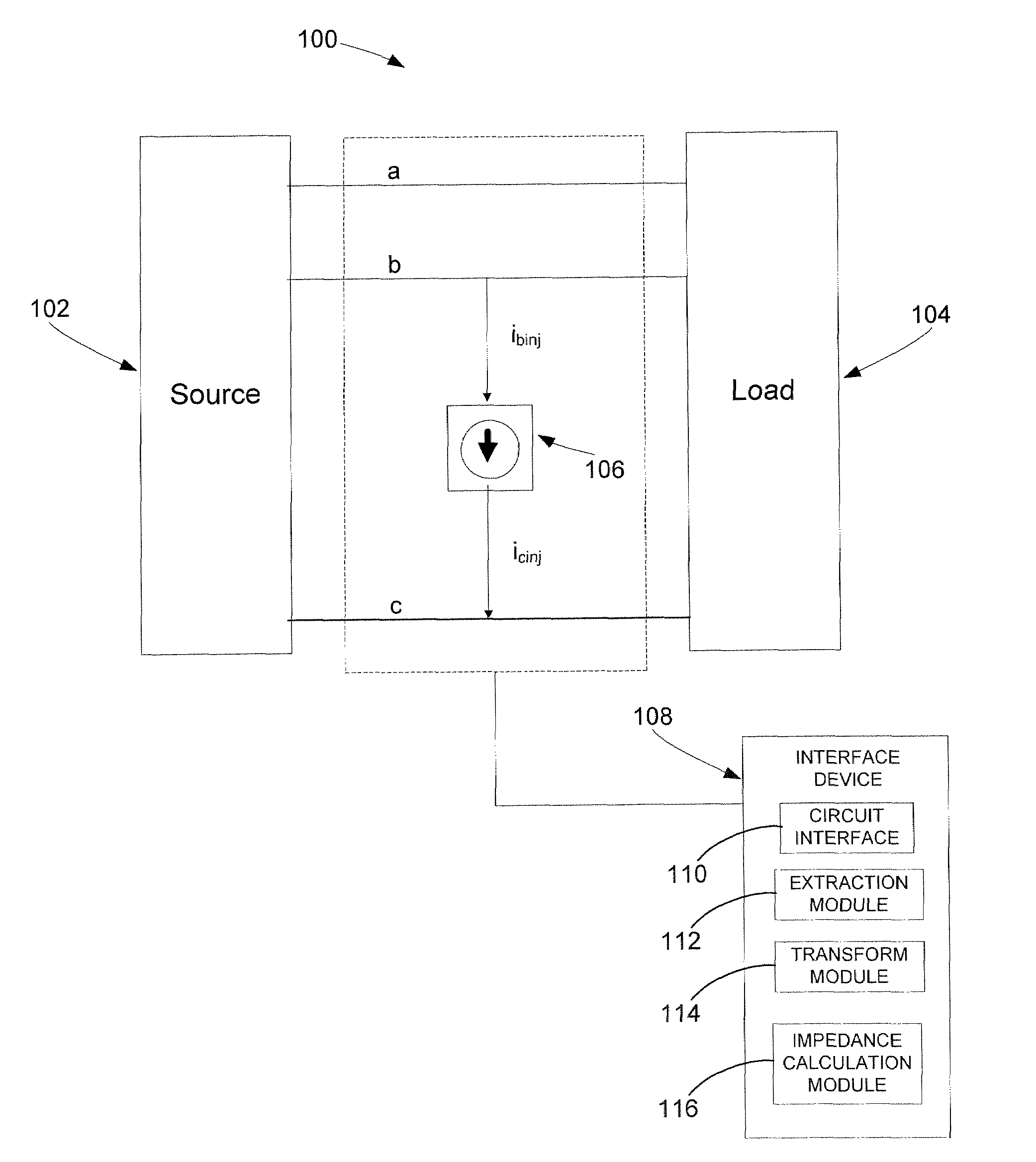
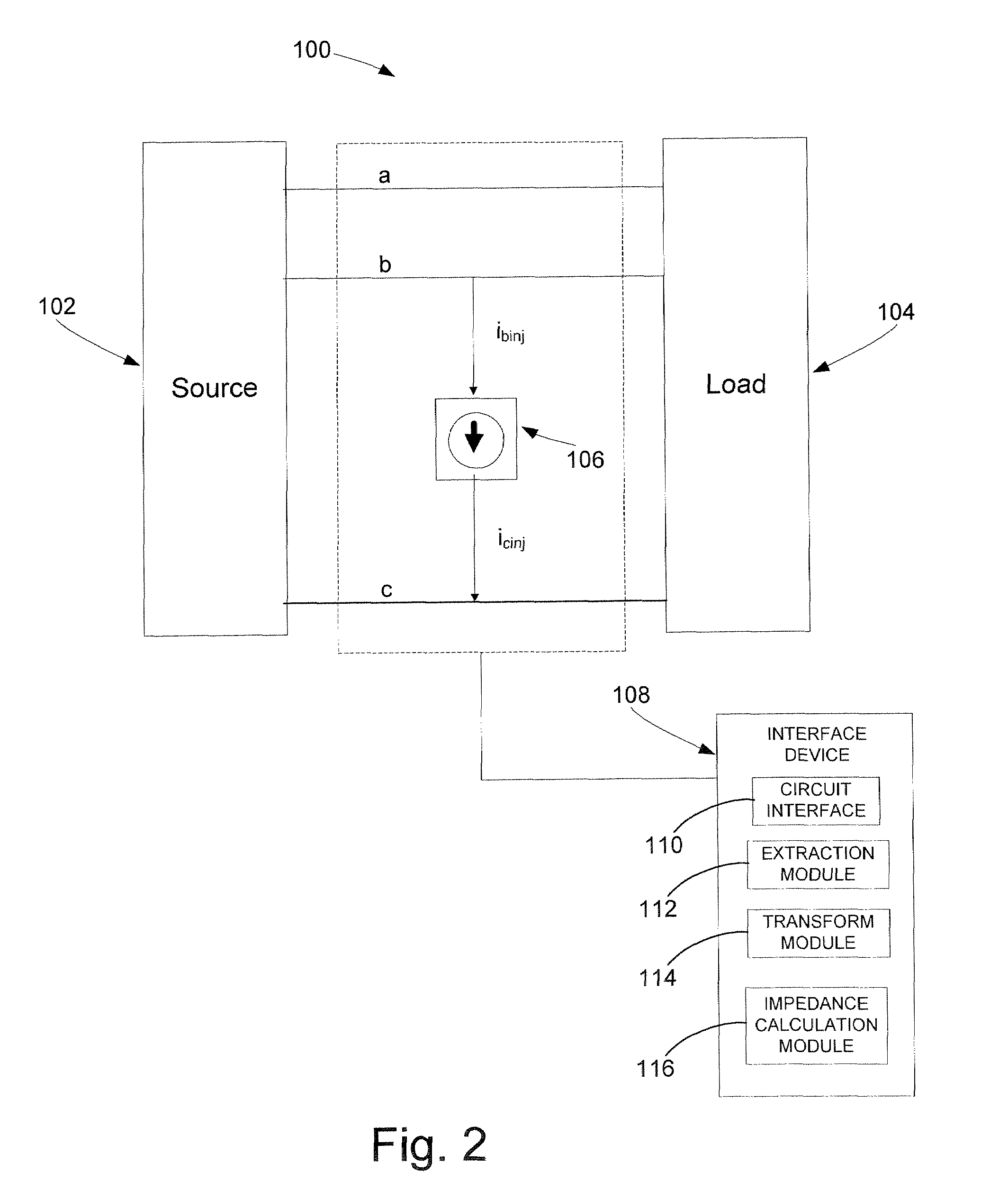
The present invention provides a method for measuring the impedance of a three-phase AC circuit using line-to-line current injection. The method involves injecting the circuit with two unbalanced line-to-line shunt currents at different frequencies, and then transforming the resulting line voltages and phase currents to a synchronous reference frame. The impedance and admittance of the source and load portions of the circuit can then be calculated using the transformed data. The technical effect of this invention is to provide a reliable and accurate method for measuring the impedance of a three-phase AC circuit.

Problems solved by technology

Although these components improve the performance of a power system, they are prone to instability due to their high efficiency and constant power characteristics which may lead to a negative impedance nature.
The instability of these components affects the stability of the overall power system.
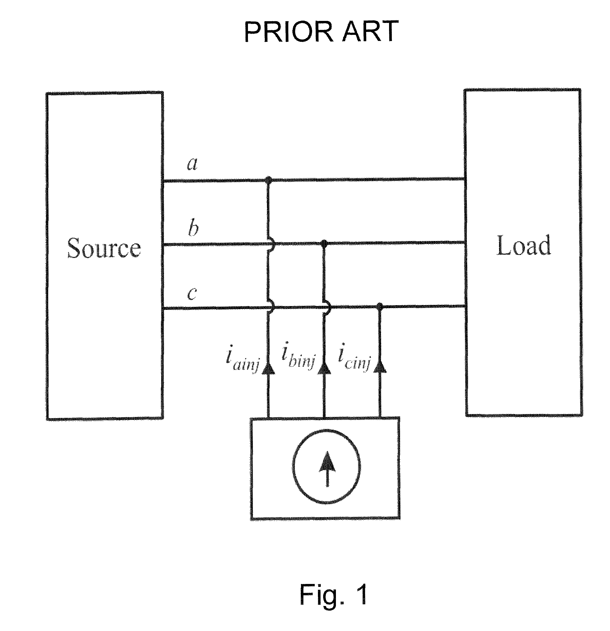
However, prior current injection techniques of three phase ac circuits, as illustrated in FIG. 1, are not very efficient.
Some of the problems caused by prior current injection techniques in three phase ac circuits are that the current must be injected at all phases of the circuit.
Additionally, hardware implementation is difficult because of a complex hardware configuration.
Further, the current being injected in the circuit is difficult to control.
These problems tend to limit the effectiveness of prior art current injection techniques of multi-phase ac circuits in applications where efficient and accurate determinations of power system stability is desirable.

Method used


Image

  • Impedance measurement using line-to-line current injection
  • Impedance measurement using line-to-line current injection
  • Impedance measurement using line-to-line current injection

Examples


example 1

[0080]FIG. 5 illustrates a three phase ac circuit injected by a current injection device. In the example, the injection device is a chopper circuit. Further, in the example a line-to-line chopper circuit injection was simulated for the three phase ac circuit shown in FIG. 5 using Advanced Continuous Simulation Language (ACSL). A fixed-frequency (60 Hz) ac power source with input inductors is used to represent a utility grid or a d-q synchronous generator. The source is connected to an R-L load through a R-C filter. The injection circuit was placed after the R-C filter and before the R-L load. Therefore, the source impedance measured in this system is composed of source R-L circuit and R-C filter. The load impedance is a simple R load circuit. The frequency was swept from 48-Hz to 4995 Hz and the source impedance and load admittance was extracted for each frequency. FIG. 6a graphically depicts source impedances determined from simulation using chopper circuit current injection. FIG. ...


PUM


Abstract

An unbalanced line-to-line current is injected at an injected frequency in a three-phase ac circuit. A first set of voltages and currents are obtained. A first set of transformed voltages and transformed currents are produced. The circuit is injected with a second unbalanced line-to-line current at a frequency linearly independent of the injected frequency. A second set of voltages and current are obtained. A second set of transformed voltages and transformed currents are produced The impedance of a source portion and a load portion of the circuit are calculated using the first and second set of transformed voltages, and the first and second set of transformed currents.

Description

CROSS-REFERENCE TO RELATED APPLICATIONS[0001]This application claims the benefit of U.S. Provisional Application No. 60 / 849,559, filed Oct. 5, 2006, which is incorporated herein by reference in its entirety.FEDERALLY SPONSORED RESEARCH OR DEVELOPMENT[0002]This invention was made in part with Government support under United States Department of Defense Contract number N00024-02-C-4056. The United States Government has certain rights in the invention.BACKGROUND OF THE INVENTION[0003]The invention relates generally to the field of power systems, and more particularly to impedance measurement techniques for determining the stability of power systems.[0004]Power systems are incorporating a greater degree of electronic circuits, power electronic converters and electronic switching sources and loads. Although these components improve the performance of a power system, they are prone to instability due to their high efficiency and constant power characteristics which may lead to a negative ...

Claims


Application Information

Patent Timeline
Patent Type & Authority Patents(United States)
IPC IPC(8): G01R27/28
CPCG01R27/16
Inventor BELKHAYAT, MOHAMEDHUANG, JINGCORZINE, KEITH
Owner UNIVERSITY OF MISSOURI
Learn More