Inverter system

a current detection and inverter technology, applied in the direction of electric generator control, dynamo-electric converter control, dynamo-electric gear control, etc., can solve the problem of difficult detection of the fundamental wave component of ac current, and achieve the effect of improving the precision of the motor output torqu

Inactive Publication Date: 2007-10-18
BROADCOM CORP +1
View PDF6 Cites 114 Cited by
  • Summary
  • Abstract
  • Description
  • Claims
  • Application Information

AI Technical Summary

Benefits of technology

[0010]An object of the present invention is to provide a current detection method of observing the DC bus current of the inverter and finding the AC output current without being influenced by pulsating components contained in the AC current.
[0011]Another object of the present invention is to provide a current detection method capable of improving the precision of the motor output torque by detecting the fundamental wave component from the motor current containing pulsating components and using it for control.

Problems solved by technology

Therefore, the observation is affected by the pulsating components and it is difficult to detect the fundamental wave component of the AC current.

Method used


Image

  • Inverter system
  • Inverter system
  • Inverter system

Examples


Embodiment Construction

[0028]Hereafter, an embodiment of the present invention will be described in detail with reference to the drawings.

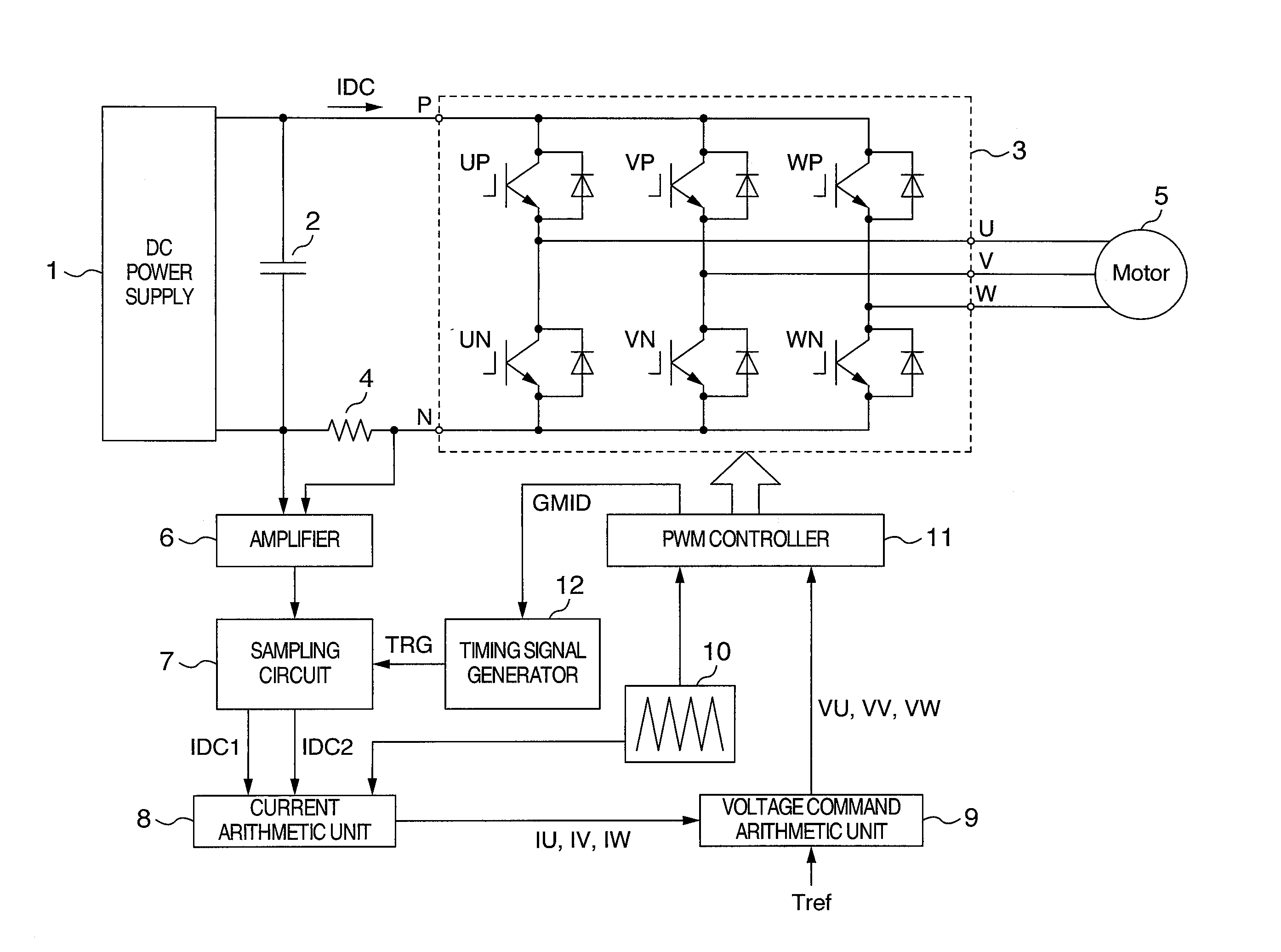
[0029]FIG. 1 shows a configuration of the present embodiment. A capacitor 2 for DC voltage smoothing is connected between a positive side terminal and a negative side terminal of a DC power supply 1. A DC positive side terminal P of an inverter 3 is connected to a positive side terminal of the capacitor 2. A DC negative side terminal N of the inverter 3 is connected to a negative side terminal of the capacitor 2 via a DC shunt resistor 4. AC terminals of an AC motor 5 to be controlled are connected to AC output terminals U, V and W of the inverter 3. The AC motor 5 is driven with power supplied by the inverter 3. A voltage is generated across the DC shunt resistor 4 by a current IDC flowing through a DC bus. An amplifier 6 amplifies the voltage across the DC shunt resistor 4. In FIG. 1, the DC shunt resistor 4 is attached to a DC bus of negative side. Even if the DC shu...


PUM


Abstract

When finding a current on an AC side of an inverter by observing that on a DC side, a current that is not affected by pulsating components contained in the AC current must be detected. Timing of change of a gate signal for driving a switch element of a phase having an intermediate magnitude among three-phase voltage command signals to ON/OFF is used as a reference time point for DC bus current detection. DC bus currents sampled T1 before and T2 after the reference time point are designated as IDC1 and IDC2, respectively. A detected current value of a maximum voltage phase is computed by using IDC2 and IDC1 respectively in an increase period and a decrease period of a carrier signal alternately. A detected current value of a minimum voltage phase is computed by using IDC1 and IDC2 respectively in an increase period and a decrease period alternately.

Description

BACKGROUND OF THE INVENTION[0001]The present invention relates to a current detection method for an inverter which drives a synchronous motor or an induction motor.[0002]The inverter is an apparatus for converting a DC voltage to an AC voltage by using the pulse width modulation. The inverter is widely used to drive an AC motor such as a synchronous motor or an induction motor.[0003]The AC output current of the inverter has a waveform obtained by superposing a high frequency pulsating component on an AC fundamental wave component. (By the way, the pulsating component is a component generated because the output voltage of the inverter is subjected to pulse width modulation.) The magnitude of the generated torque of the driven motor depends upon the magnitude and phase of the fundamental wave component of the AC current. When controlling the generated torque of the motor with high precision, therefore, it becomes necessary to extract only the fundamental wave component of the AC curre...

Claims


Application Information

Patent Timeline
Patent Type & Authority Applications(United States)
IPC IPC(8): H02P27/04H02P21/22H02P27/06H02P27/08
CPCH02M2001/0009H02M7/5395H02P27/08H02M1/0009
Inventor SAKAMOTO, KIYOSHIAOYAGI, SHIGEHISASUZUKI, TAKAHIRO
Owner BROADCOM CORP
Why Eureka
Try Eureka