Method for distributed clipping outside of view volume

Active Publication Date: 2010-06-29
VIVANTE CORPORATION
View PDF9 Cites 17 Cited by
  • Summary
  • Abstract
  • Description
  • Claims
  • Application Information

AI Technical Summary

Problems solved by technology

Such an implementation can cause a bottleneck in the pipeline because of the large number of computation required for performing clipping/culling.
The disadvantage is that all the 3D objects need to be transformed to screen space, even the objects outside of

Method used


Image

  • Method for distributed clipping outside of view volume
  • Method for distributed clipping outside of view volume
  • Method for distributed clipping outside of view volume

Examples


Embodiment Construction

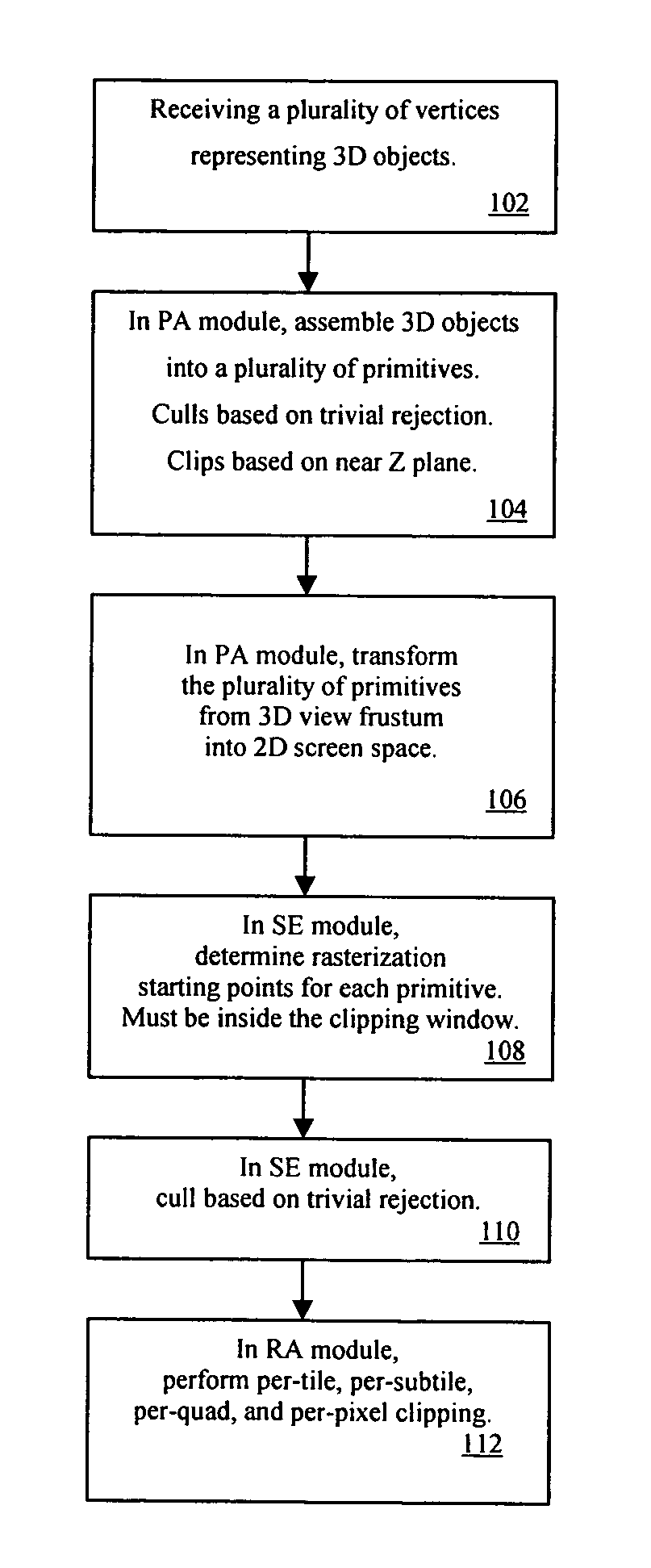
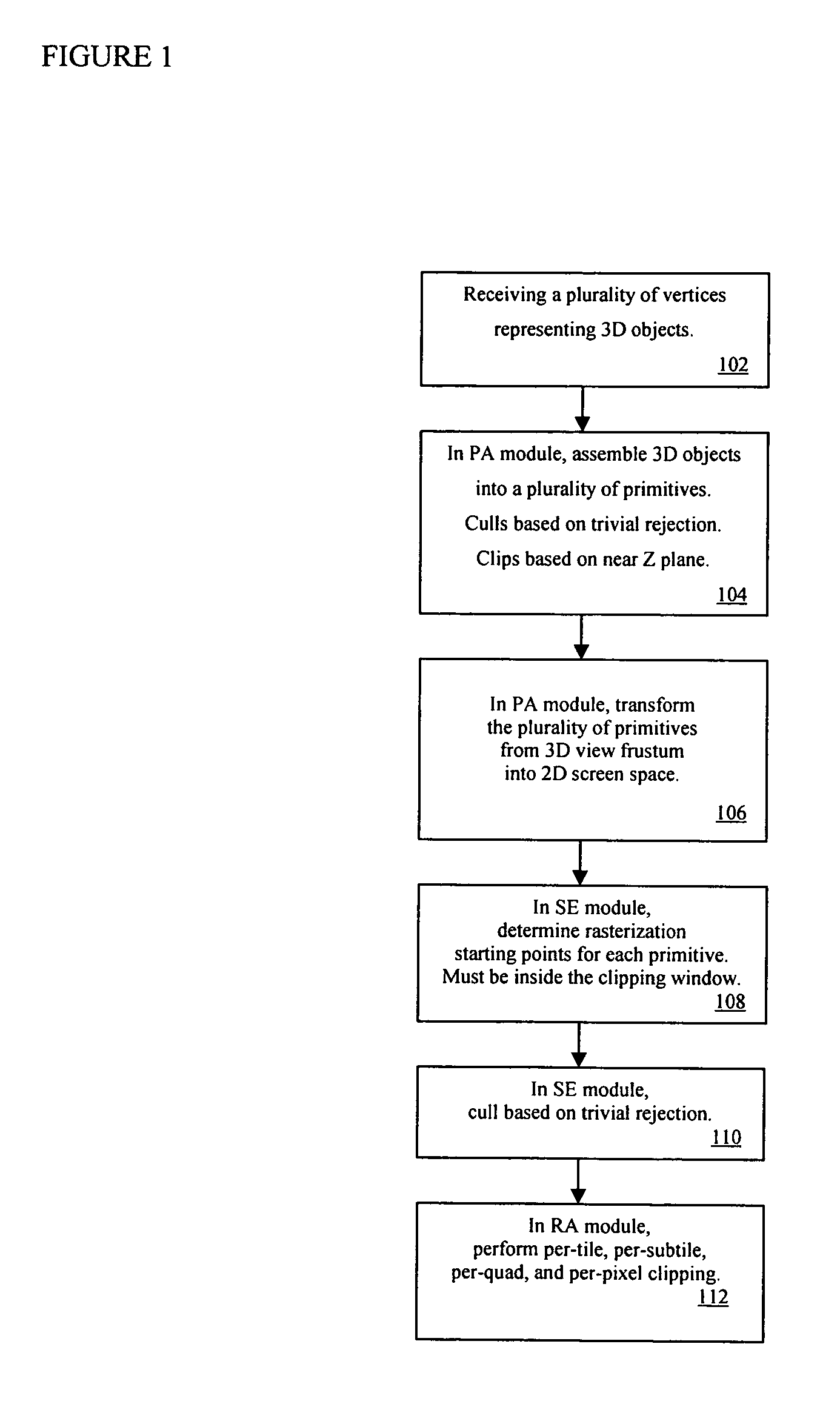
[0014]FIG. 1 is a flow chart diagram illustrating an overall clipping / culling procedure of the graphics processing pipeline according to one embodiment of the present invention. As an example, the graphics processing pipeline includes the PA module, the SE module and the RA module. Here, step 102 receives multiple vertices representing 3D objects. In some examples, the vertices may be received from a vertex shader module which computes these vertices for representing 3D objects. Step 104 converts these 3D objects from vertices to geometric primitives, such as points, line segments (hereafter referred to as lines), triangles, or other appropriate geometric shapes. In an example, the PA module is configured in a triangle mode. In triangle mode, the vertices are converted into multiple triangles before any further processing. In another example, the PA module is configured in a line mode and converts the vertices into multiple lines before any further processing. In yet another example...


PUM


Abstract

A distributed clipping scheme is provided, view frustum culling is distributed in several places in a graphics processing pipeline to simplify hardware implementation and improve performance. In general, many 3D objects are outside viewing frustum. In one embodiment, clipping is performed on these objects with a simple algorithm in the PA module, such as near Z clipping, trivial rejection and trivial acceptance. In one embodiment, the SE and RA modules perform the rest of clipping, such as X, Y and far Z clipping. In one embodiment, the SE module performs clipping by way of computing a initial point of rasterization. In one embodiment, the RA module performs clipping by way of conducting the rendering step of the rasterization process. This approach distributes the complexity in the graphics processing pipeline and makes the design simpler and faster, therefore design complexity, cost and performance may all be improved in hardware implementation.

Description

CROSS REFERENCE TO RELATED APPLICATIONS[0001]The present application relates to U.S. patent application Ser. No. 11 / 592,799, filed on Nov. 3, 2006, entitled “HIERARCHICAL TILE-BASED RASTERIZATION ALGORITHM” which is incorporated herein by reference.BACKGROUND[0002]1. Field of the Invention[0003]The invention relates generally to the field of computer systems and more particularly to 3D computer graphics processor.[0004]2. Description of Related Art[0005]In 3D computer graphics, the view frustum is the region of a three dimensional space in the modeled world that may appear on a computer display screen represented by the 2D screen space (hereinafter also referred to as the screen space). The exact shape of the view frustum may vary, e.g. it may be a rectangular cube, a rectangular pyramid, or other suitable geometric shape. In an example, the frustum may be formed with six planes: near plane, far plane, +X plane, −X plane, +Y plane, and −Y plane. The planes that cut the view frustum ...

Claims


Application Information

Patent Timeline
IPC IPC(8): G09G5/00G06T15/30
CPCG06T15/30G06T15/10G06T17/00
Inventor CAI, MIKETAN, LINGARRITSEN, FRIDOCHEN, MING
Owner VIVANTE CORPORATION
Why Eureka
Try Eureka