Method for attaching a compensator assembly to a firearm

a compensator and firearm technology, applied in the field of compensator assemblies for firearms, can solve the problems of affecting accuracy, affecting the accuracy of subsequent discharges, and muscular fatigue from the jump (or), and achieve the effect of effectively transferring quick and efficient interchange, and effective transfer of the discharge force of a firearm

Inactive Publication Date: 2010-07-06
SMITH & WESSON INC
View PDF22 Cites 18 Cited by
  • Summary
  • Abstract
  • Description
  • Claims
  • Application Information

AI Technical Summary

Benefits of technology

[0009]It is another object of the present invention to provide a compensation system for a firearm that does not require the milling of discharge slots in the barrel of the firearm.
[0012]It is another object of the present invention to provide a compensation system for a firearm that enables compensator assemblies of differing configurations to be utilized.
[0013]It is another object of the present invention to provide a compensation system for a firearm that permits for the quick and efficient interchange between compensator assemblies of differing configurations.
[0014]It is another object of the present invention to provide a compensation system for a firearm that effectively transfers the discharge force of a firearm.
[0015]It is another object of the present invention to provide a compensation system for a firearm that effectively transfers the discharge force of a firearm to the body of the firearm.
[0017]It is another object of the present invention to provide a compensation system for a firearm that may assist in lower production and maintenance costs.

Problems solved by technology

As will be appreciated, this movement may affect the accuracy of a given shot while also making the accuracy of subsequent discharges problematic.
Moreover, muscular fatigue from the jump (or ‘kick’) of the firearm, following the discharge of the firearm, is also generated.
While successful to a certain degree, the milling of compensator discharge slots in the barrel of a firearm tend to deface the barrel itself, while also interfering somewhat with the effectiveness of the lands and grooves, if present, of any rifling that may be milled on the interior surface of the barrel.
Moreover, known compensators oftentimes do not produce the most optimized performance characteristics due to the size and location of the discharge slots.

Method used


Image

  • Method for attaching a compensator assembly to a firearm
  • Method for attaching a compensator assembly to a firearm
  • Method for attaching a compensator assembly to a firearm

Examples


Embodiment Construction

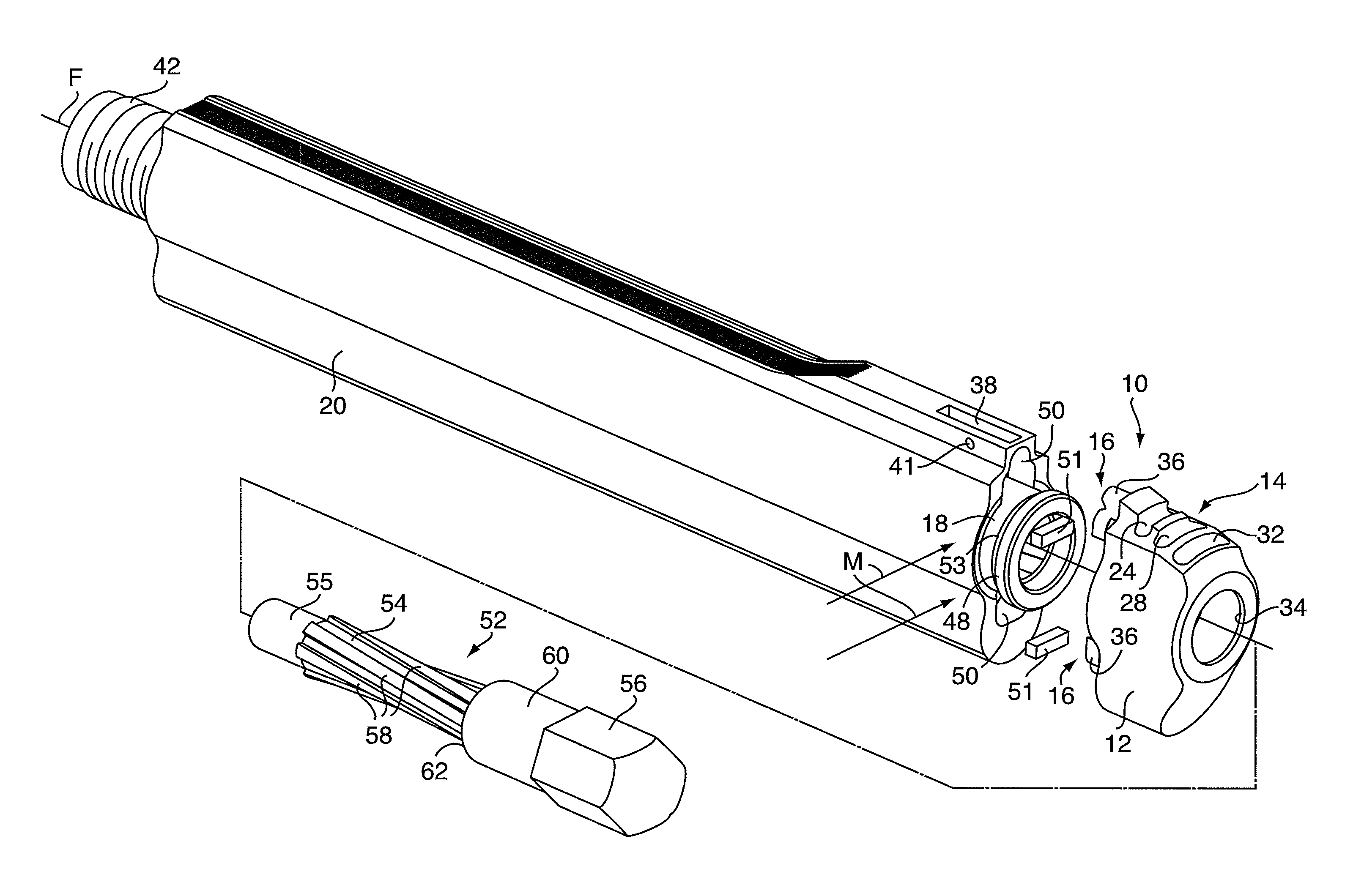
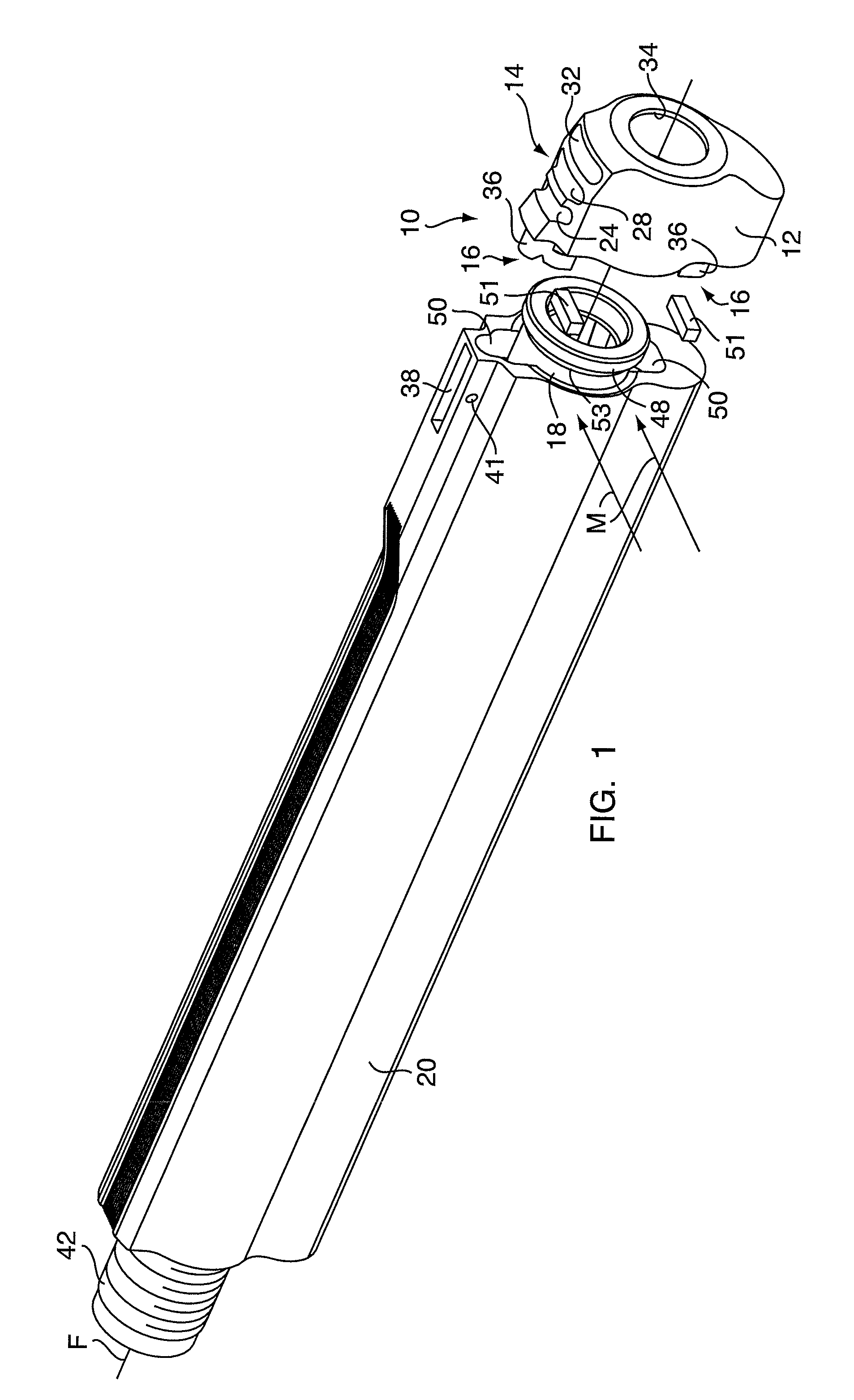
[0035]FIG. 1 is a partially exploded, isometric view of a compensation system for a firearm having a firearm compensator assembly 10, according to one embodiment of the present invention. As shown in FIG. 1, the compensator assembly 10 includes a housing 12, a plurality of arcuate gas discharge slots 14 and a mating assembly 16 that facilitates the mounting of the housing 12 onto a firearm barrel 18. In the embodiment illustrated in FIG. 1, the barrel 18 defines a firing axis F and is removably disposed with a firearm shroud 20, although alternative designs, such as but not limited to fixed barrel and shroud designs, are equally contemplated by the present invention.

[0036]The shroud 20 may be fabricated from a material having a density substantially less than the density of the material from which the barrel 18 is made, for reduced firearm weight. The upper surface of the barrel shroud 20 is substantially flat and has an axially elongated, upwardly open, sight receiving groove 38 fo...


PUM


Abstract

A method for releasably attaching a compensator assembly adjacent a muzzle end of a barrel of a firearm. The compensator assembly includes an attachment means on its rear end. The barrel has a firing axis and includes a threaded end opposite the muzzle end and defines a recess formed adjacent the muzzle end. The firearm itself has a frame defining a threaded aperture. The method includes moving the attachment means into engagement with the recess; tensioning the attachment means within the recess in a direction substantially parallel to the firing axis; inserting a mating tool into the muzzle end of the barrel; rotating the barrel via the mating tool, thereby causing the threaded end of the barrel to threadedly engage with the threaded aperture; and halting the rotation of the barrel via the mating tool when a predetermined torque is achieved.

Description

CROSS REFERENCE TO RELATED APPLICATIONS[0001]This is a Divisional application of pending U.S. application Ser. No. 10 / 773,500 filed on Feb. 6, 2004, and claims the benefit of U.S. Provisional Application Ser. No. 60 / 446,125, filed on Feb. 10, 2003; U.S. Provisional Application Ser. No. 60 / 446,629, filed on Feb. 11, 2003; and U.S. Utility Pat. No. 6,266,908, issued on Jul. 31, 2001, all of which are hereby incorporated by reference in their entireties.FIELD OF THE INVENTION[0002]This invention relates in general to a compensation system for a firearm, and deals more particularly with a method for releasably attaching a compensator assembly adjacent a muzzle end of a barrel of a firearm.BACKGROUND OF THE INVENTION[0003]When a round of ammunition is fired from a firearm, handguns in particular, it is often the case that the barrel end of the firearm will ‘jump’, or kick upwards, as a result of the discharge of the round. As will be appreciated, this movement may affect the accuracy of ...

Claims


Application Information

Patent Timeline
Patent Type & Authority Patents(United States)
IPC IPC(8): F41A21/36
CPCF41A21/28F41A21/36F41A21/38
Inventor CURRY, BRETTMIKUTA, RICHARD
Owner SMITH & WESSON INC
Why Eureka
Try Eureka