Shielding for structural support elements

a technology for supporting elements and shielding, which is applied in the direction of safes, bridges, instruments, etc., can solve the problems of affecting the safety of the structure, and the vulnerability of the structural element that is widely used in construction

Inactive Publication Date: 2010-07-06
HALLISSY GERALD +1
View PDF85 Cites 25 Cited by
  • Summary
  • Abstract
  • Description
  • Claims
  • Application Information

AI Technical Summary

Benefits of technology

[0005]According to the present invention, a shield is provided which shields an exposed structural element from, among other things, an explosive blast and ensuing fire. The shield of the present invention can be retrofitted onto existing structures or installed in new construction. The shield includes at least two pre-formed shield members that are assembled to enclose at least a portion of a structural element to provide protection to the enclosed portion.
[0006]The assembled shield protects structural elements from blast energy, ballistic threats, and flying debris. The structural member can be a structural component of a building or a vehicle, or, for example, a tension cable (or cables) which supports suspension bridges and the like, e.g., viaducts, etc. And the shield members can be made so that they interlock, e.g., can be slidably interlocked, around the enclosed portion of the structural member.
[0007]The energy absorbing shield can, in one primary embodiment, include mainly an ultra high strength concrete. In a second primary embodiment, the shield can include a chassis and at least one ballistic liner, preferably an ultra high strength concrete, disposed on the chassis such that the chassis is more proximal to the structural member than the ballistic liner. In both embodiments the shield includes at least two shield members which are capable of being assembled to enclose at least a portion of the structural member to provide protection to the enclosed portion from an explosive blast and ensuing fire.

Problems solved by technology

Exposed structural elements of buildings and transportation infrastructure are particularly vulnerable targets for terrorist activity.
One particularly vulnerable structural element that is widely used in construction is tension cables.
While designs employing such tension cables always employ a certain degree of redundancy, damages to numerous cables can have a catastrophic effect.
Damage in the case of explosive devices is particularly problematic, since even small “nicks” in highly tension metal can create failure modes which are largely absent in non-tension structures.

Method used


Image

  • Shielding for structural support elements
  • Shielding for structural support elements
  • Shielding for structural support elements

Examples


Embodiment Construction

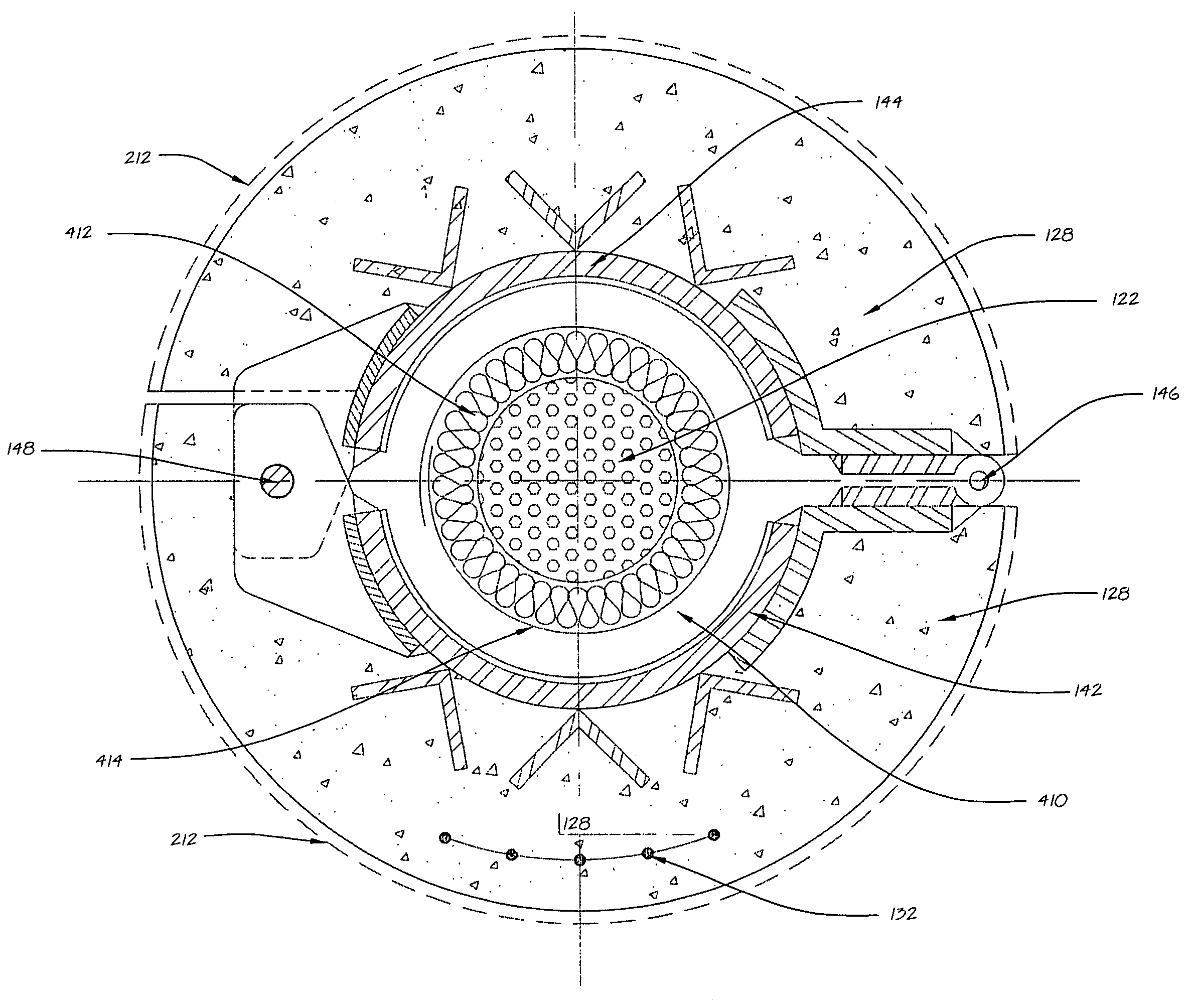
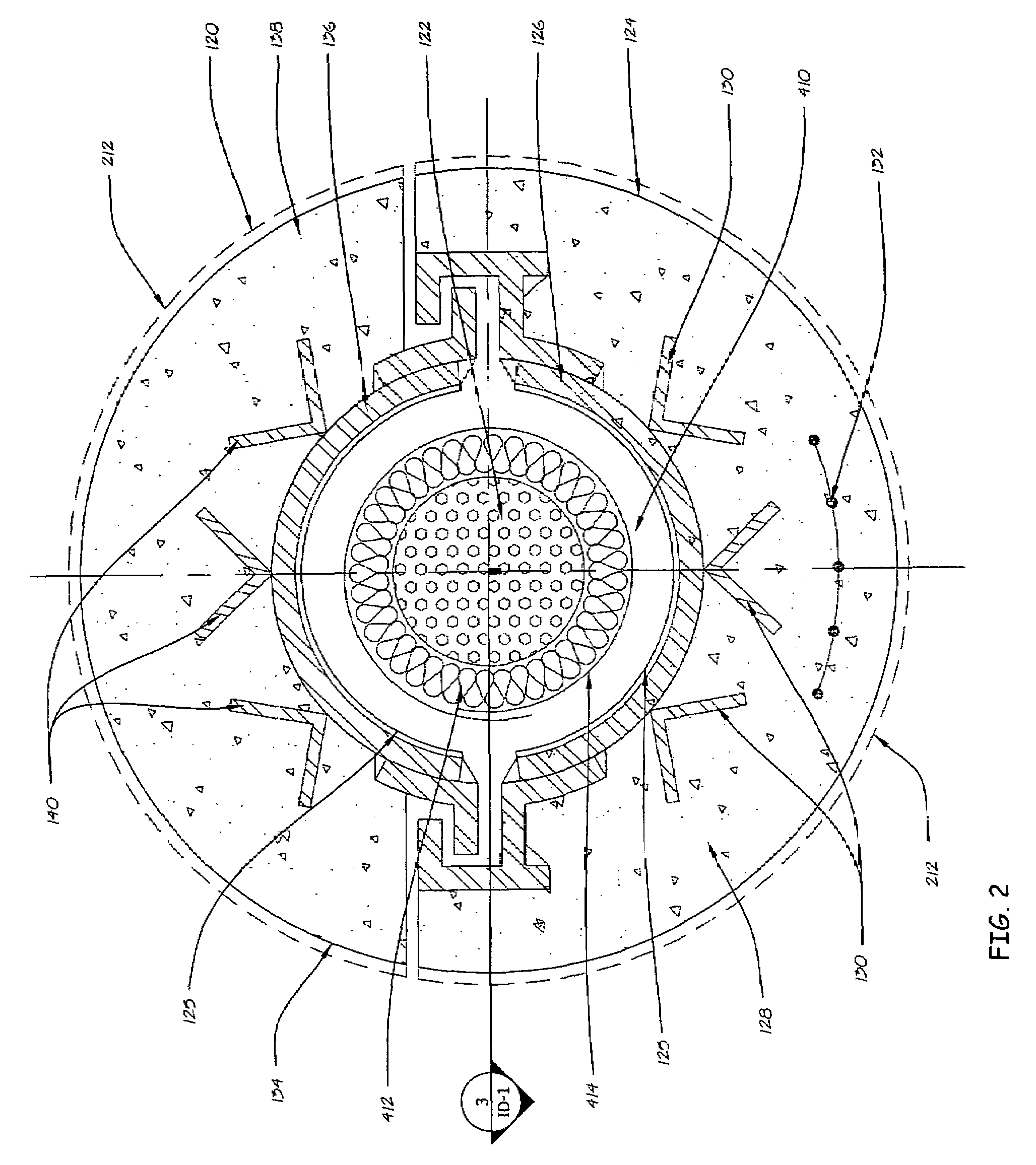
[0028]The present invention provides a shield that is relatively inexpensive and is easily constructed, which shields an exposed structural element from an explosive blast and fire. The shield can be retrofitted onto existing structures or installed in new construction. One primary embodiment of the invention provides a shield that includes at least two shield members made mainly of pre-cast ultra high strength concrete. The shield members are capable of being assembled to enclose at least a portion of the structural member to provide protection to the enclosed portion from an explosive blast.

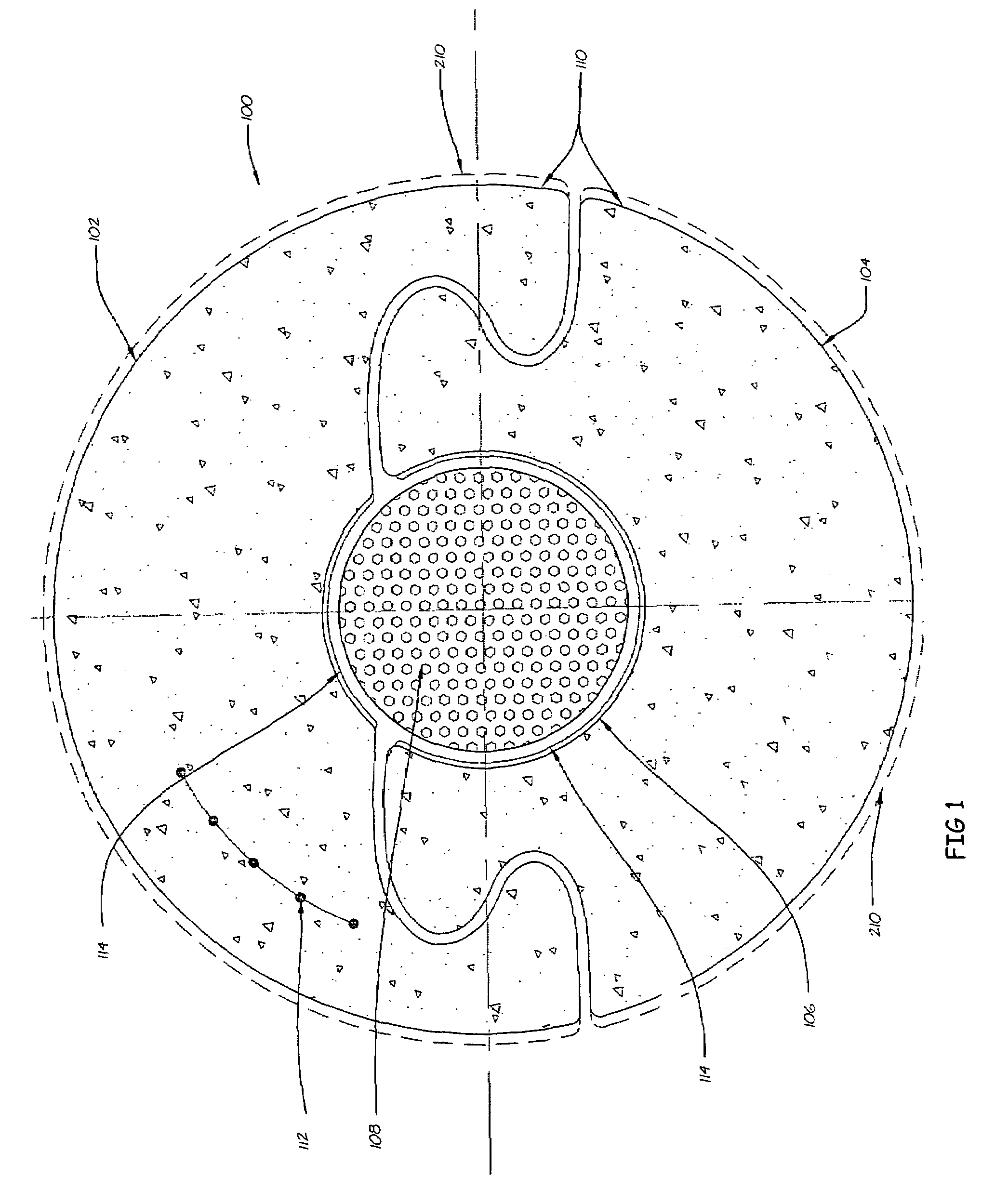
[0029]As shown in FIG. 6, in one preferred embodiment, the structural element or member is a tension cable 502. Tension cables are well known and details of structures using such cables can be obtained from numerous textbooks and treatises on civil engineering and architecture. Numerous variants are possible, and most cables for heavy structures and / or tall structures such as radio or televisio...


PUM


Abstract

A shield for shielding a structural member from an explosive blast or accidental or malicious destruction is provided. The shield includes a plurality of shield members which include cast ultra high strength concrete, wherein the shield members are capable of being assembled to enclose at least a portion of the structural member to provide protection to the enclosed portion from, for example, an explosive blast. In one embodiment, the shield members include a chassis, at least one ballistic liner disposed on the energy absorbing layer, and a concrete-integrating structure.

Description

BACKGROUND OF THE INVENTION[0001]The invention relates to blast and ballistic shielding for structural support elements for buildings, bridges, transportation infrastructure and vehicles, and in particular to pre-formed shielding which provides protection from the effects of blast(s) from explosives or accidental or malicious destruction.[0002]Due to increased threats and awareness of potential terrorist activities, increased attention is being given to protecting structures of all types against damage from fire, explosion, and other threats, malicious and accidental, to structural elements of buildings and the like. An example is U.S. Pat. No. 6,960,388 to Hallissy, et al. which discloses and claims flexible but intumescent coatings for an electrical conduit which, when exposed to intense heat, forms an expandable insulative layer about the conduit. This provides increased protection for electrical and communication cables and wires which the conduit encases.[0003]There is a need f...

Claims


Application Information

Patent Timeline
Patent Type & Authority Patents(United States)
IPC IPC(8): F41H5/24
CPCE01D19/16E04H9/04F41H5/0442F41H5/0471F41H5/24F42D5/04
Inventor HALLISSY, GERALDHIGBIE, WILLIAM
Owner HALLISSY GERALD
Why Eureka
Try Eureka