Electric power steering device

a technology of electric power steering and worm shaft, which is applied in the direction of gearing, transportation and packaging, hoisting equipment, etc., can solve the problems of increasing production costs, affecting the durability of the worm shaft, so as to reduce stress, improve durability, and increase the stress load

Inactive Publication Date: 2010-07-06
JTEKT CORP
View PDF28 Cites 23 Cited by
  • Summary
  • Abstract
  • Description
  • Claims
  • Application Information

AI Technical Summary

Benefits of technology

[0011]If a pair of resilient tongues for biasing the driving gear toward the driven gear were provided on the respective movement restriction portions, a stress load to be exerted on one of the resilient tongues would be reduced, and a stress load to be exerted on the other resilient tongue would be correspondingly increased. The present mode enables eliminating the resilient tongue which receives the relatively increased stress load, and arranging only the resilient tongue which receives the relatively reduced stress, to improve the durability. Further, the main portion can be formed of a thin plate, so that the size reduction of the device can be achieved.

Problems solved by technology

However, when vibrations are inputted from a road surface to tires while traveling under bad road conditions, for example, rattle occurs between the worm shaft and the worm wheel due to the backlash.
However, this operation is cumbersome, thereby increasing production costs.
In this case, the backlash amount is liable to be changed by the wear of the teeth of the worm wheel and the expansion and contraction of the worm wheel due to a temperature change, moisture absorption and the like.
As a result, the device has an increased in size.
Similar problems are also found in electric power steering devices utilizing a common gear mechanism other than the worm shaft and the worm wheel.

Method used


Image

  • Electric power steering device
  • Electric power steering device
  • Electric power steering device

Examples


Embodiment Construction

[0019]Preferred embodiments of the present invention will be described with reference to the attached drawings.

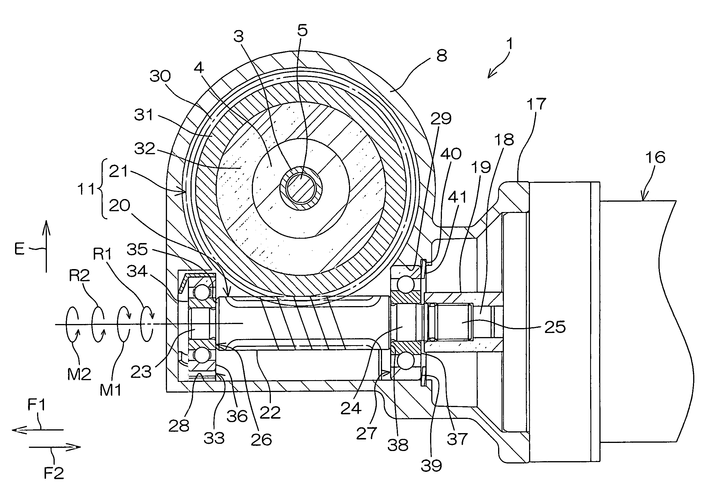
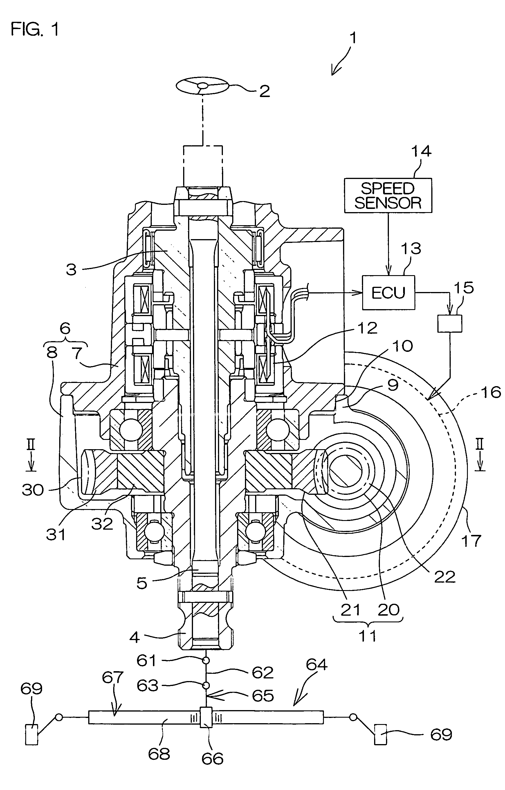
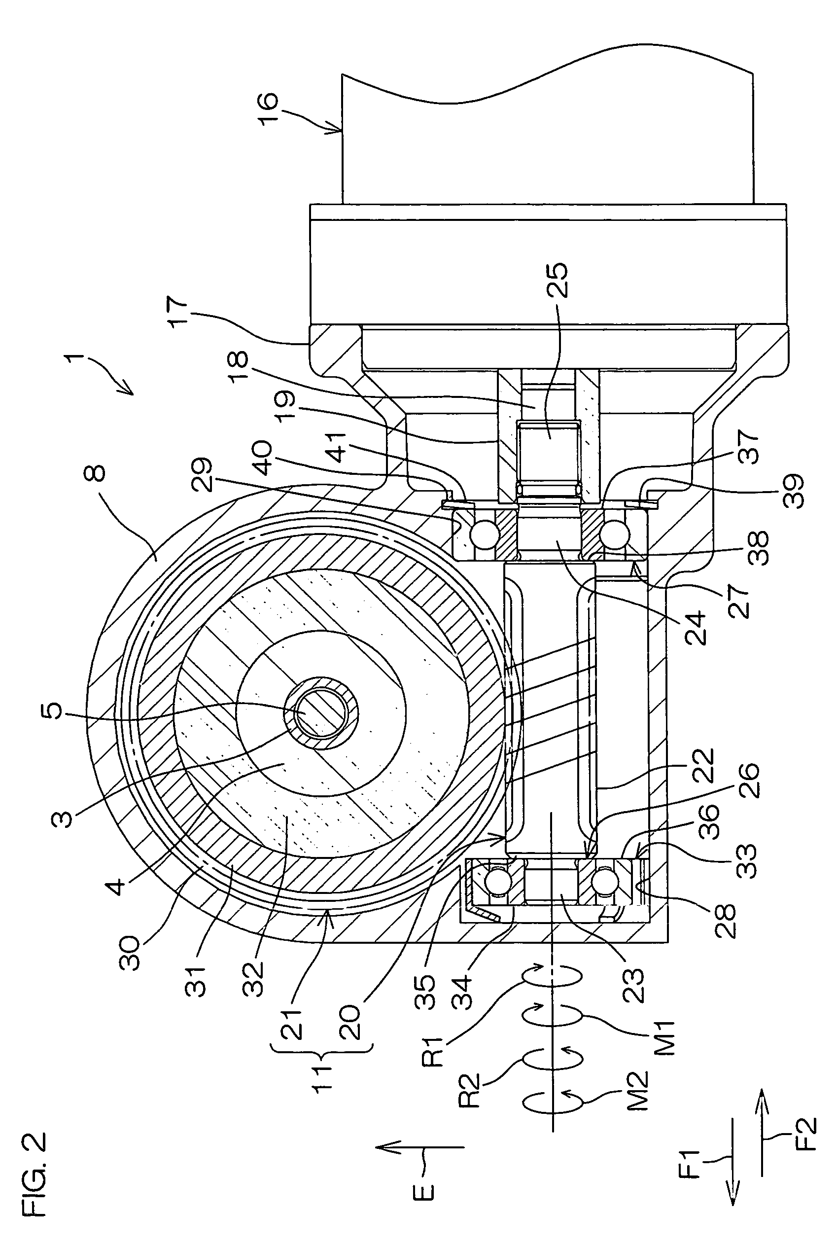
[0020]FIG. 1 is a schematic sectional view of an electric power steering device 1 according to one embodiment of the present invention. FIG. 2 is a sectional view taken along a line II-II in FIG. 1.

[0021]Referring to FIG. 1, the electric power steering device 1 includes a first steering shaft 3 defined as an input shaft coupled to a steering member 2 such as a steering wheel, and a second steering shaft 4 defined as an output shaft coupled to a steering mechanism 64 via a universal joint 61, an intermediate shaft 62 and a universal joint 63. The first and second steering shafts 3,4 are coaxially coupled to each other via a torsion bar 5.

[0022]The steering mechanism 64 comprises, for example, a rack and pinion mechanism. More specifically, the steering mechanism 64 includes a pinion 66 provided around a pinion shaft 65 coupled to the universal joint 63, and a rack 68 provide...


PUM


Abstract

An electric power steering device (1) is provided which transmits output rotation of an electric motor for generating a steering assist force (16) to a steering mechanism (64) via a driving gear (22) and a driven gear (21). A housing (8) has a support hole (28) for supporting one end portion (23) of a shaft (20) co-rotatable with the driving gear (22) via a bearing (26) in such a manner as to permit the one end portion (23) to be offset toward the driven gear (21) radially of the driving gear (22). A biasing member (33) which biases the driving gear (22) toward the driven gear (21) includes an arcuate main portion (47) fitted around an outer peripheral surface (58) of an outer ring (36) of the bearing (26) and opposed to an inner peripheral surface (42) of the support hole (28). A pair of movement restriction portions (50, 51) which restrict circumferential movement of the main portion (47) are respectively provided at a pair of arc ends (48, 49) of the main portion (47). A resilient tongue (52) which biases the driving gear (22) toward the driven gear (21) via the bearing (26) is provided only on one of the movement restriction portions (50).

Description

TECHNICAL FIELD[0001]The present invention relates to an electric power steering device which transmits output rotation of a steering assist electric motor to a steering mechanism via a driving gear and a driven gear meshed with the driving gear.BACKGROUND ART[0002]Electric power steering devices of the aforesaid type employ a worm shaft as a driving gear and a worm wheel as a driven gear (see, for example, Japanese Unexamined Patent Publication No. 2001-108025).[0003]In general, the worm shaft and the worm wheel should be meshed with each other with proper backlash for reduction of a torque loss. However, when vibrations are inputted from a road surface to tires while traveling under bad road conditions, for example, rattle occurs between the worm shaft and the worm wheel due to the backlash.[0004]In order to minimize the torque loss and generation of the rattle, the amount of the backlash should be adjusted within a predetermined machining accuracy. That is, a proper combination o...

Claims


Application Information

Patent Timeline
Patent Type & Authority Patents(United States)
IPC IPC(8): B62D5/04F16H1/16
CPCB62D5/0409Y10T74/19623F16H2057/0213F16H57/021F16C23/08F16C27/04F16H55/24
Inventor IWASA, SOUICHIOUGITA, SHINGO
Owner JTEKT CORP
Why Eureka
Try Eureka