Sheet tray device and image forming apparatus having the sheet tray device

a technology of image forming apparatus and tray device, which is applied in the direction of thin material processing, article separation, printing, etc., can solve the problems of poor maneuverability of conventional image forming apparatus, inability to accommodate multiple media sheets of different sizes in the single tray member, and inability to achieve large-scale image forming apparatus for domestic us

Active Publication Date: 2010-07-06
BROTHER KOGYO KK
View PDF19 Cites 10 Cited by
  • Summary
  • Abstract
  • Description
  • Claims
  • Application Information

AI Technical Summary

Benefits of technology

[0012]The first aspect of the invention provides a sheet tray device that is removably introduced into a main body of an image forming apparatus through an opening of the main body, so as to hold a media sheet that is to be supplied to an image forming unit of the image forming apparatus by which an image forming operation is performed on the media sheet. The sheet tray device includes: (a) a first tray accommodating a larger or first size sheet as the media sheet; and (b) a second tray disposed on an upper side of the first tray and accommodating a smaller or second size sheet as the media sheet. The second tray includes (b-1) a support member which bridges between opposite side walls of the first tray and which is movable relative to the opposite side walls, and (b-2) a supported body pivotably supported by the support member so as to open and close an upper opening of the first tray. Each of the opposite side walls of the first tray includes first and second rail portions that extend in a rail extending direction in which the support member is movable relative to the opposite side walls. The second rail portion is located on an upper side of the first rail portion and being spaced apart from the first rail portion. The support member of the second tray includes (i) a main slide portion that is slidably held in contact with an upper surface of the first rail portion, (ii) a removal-preventing slide portion that extends through a gap or space between the first and second rail portions so as to prevent removal of the support member of the second tray from the first tray, and (iii) a rotation-preventing slide portion that is slidably held in contact with an inside or outside surface of the first rail portion so as to prevent rotation of the support member of the second tray relative to the first tray.
[0014]Further, since the removal-preventing slide portion extends through the space between the first and second rail portions, removal of the support member of the second tray from the first tray can be prevented by engagement of the removal-preventing slide portion with at least one of the first and second rail portions.
[0015]Moreover, since the rotation-preventing slide portion is slidably held in contact with the inside or outside surface of the first rail portion, it is possible to prevent rotation of the second tray relative to the first tray.
[0016]Therefore, in the present sheet tray device, it is possible to avoid problems such as rotation of the second tray relative to the first tray and removal of the second tray from the first tray, when the second tray is moved relative to the first tray.
[0020]In the image forming apparatus according to this second aspect of the invention, owing to incorporation of the sheet tray device defined in the first aspect of the invention, it is possible to enjoy the above-described technical advantages provided by the sheet tray device. That is, in the sheet tray device of the image forming apparatus, the second tray can be advantageously moved relative to the first tray without risk of rotation of the second tray relative to the first tray or removal of the second tray from the first tray.

Problems solved by technology

However, the media sheets of plurality of different sizes can not be concurrently accommodated in the single tray member.
Since such a sheet replacement operation is generally cumbersome, the conventional image forming apparatus is poor in maneuverability, particularly, for a user who has to carry out the image forming operation on the media sheets of various sizes.
However, the large-sized image forming apparatus is not feasible for a domestic use in which there is not a large space available for installation of the apparatus.
However, another problem is encountered in this double-deck sheet tray device.
The problem is that refilling the first tray with the sheets could be made difficult by the arrangement in which the second tray is disposed to cover an upper opening of the first tray.
However, the double-deck sheet tray device suffers from still another problem that the second tray could be rotated relative to the first tray or removed from the first tray during movement of the second tray relative to the first tray.

Method used


Image

  • Sheet tray device and image forming apparatus having the sheet tray device
  • Sheet tray device and image forming apparatus having the sheet tray device
  • Sheet tray device and image forming apparatus having the sheet tray device

Examples


Embodiment Construction

[0052]There will be described an image forming apparatus 100 that is constructed according to an embodiment of the invention. The image forming apparatus 100 is a multi function device having various functions such as printer function, scanner function, color copier function and facsimile function.

1. Basic Construction of Image Forming Apparatus 100

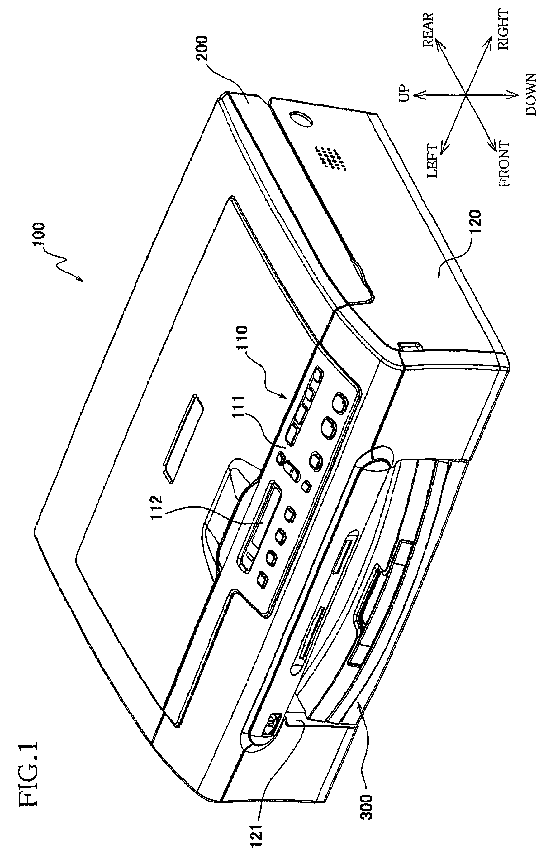
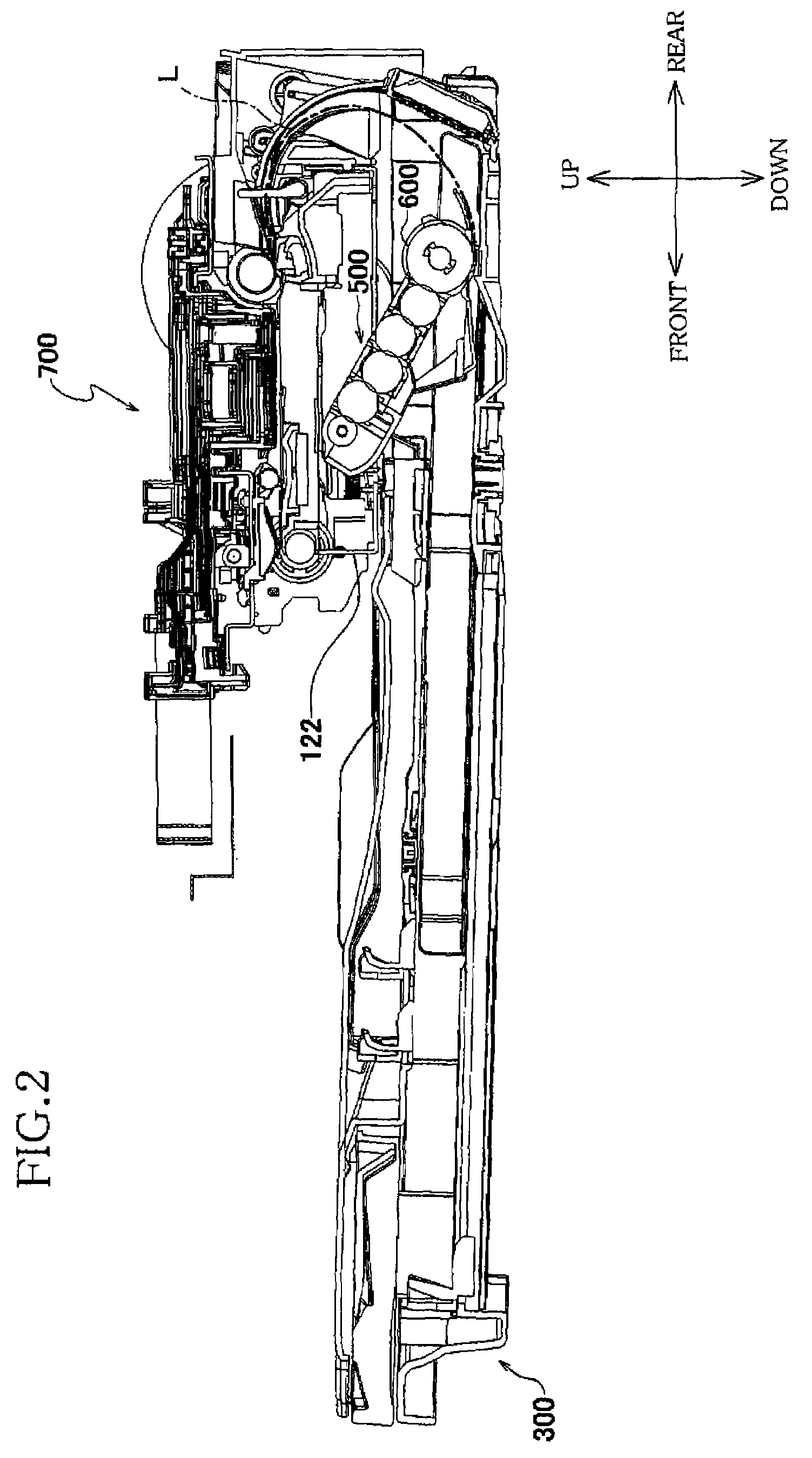
[0053]FIG. 1 is a perspective view of the image forming apparatus 100. FIG. 2 is a side view partially in cross section of a sheet supplying unit 500 and an image forming unit 700 that are incorporated in the image forming apparatus 100 of FIG. 1. The image forming apparatus 100 has a main body in the form of a casing body 120 that is provided by a rectangular parallelepiped box-like body made of a resin. This apparatus 100 is installed for use, with its front portion and upper portion as seen in FIG. 1 facing forwardly and upwardly, respectively.

[0054]An operator's control panel 110 is provided on an upper surface of a front portion of t...


PUM


Abstract

A sheet tray device including (a) a first tray and (b) a second tray which is disposed on an upper side of the first tray and which includes (b-1) a support member which bridges between opposite side walls of the first tray and which is movable relative to the opposite side walls, and (b-2) a supported body pivotably supported by the support member. Each of the opposite side walls includes a first rail portion and a second rail portion that is located on an upper side of the first rail portion. The support member includes (i) a main slide portion that is slidably held in contact with an upper surface of the first rail portion, (ii) a removal-preventing slide portion that extends through a space between the first and second rail portions, and (iii) a rotation-preventing slide portion that is slidably held in contact with a side surface of the first rail portion. Also disclosed is an image forming apparatus including the sheet tray device.

Description

[0001]This application is based on Japanese Patent Application No. 2006-048514 filed on Feb. 24, 2006, the content of which is incorporated hereinto by reference.BACKGROUND OF THE INVENTION[0002]1. Field of the Invention[0003]The present invention relates to a sheet tray device for accommodating a media sheet such as paper sheet, OHP sheet, envelop and postal card, and also an image forming apparatus including such a sheet tray device.[0004]2. Discussion of Related Art[0005]It is common that a sheet tray device for use in an image forming apparatus is provided by a single tray member that is removably introduced into a main body of the image forming apparatus, as disclosed in JP-2005-314067A.[0006]The sheet tray device is required to accommodate the media sheets of various sizes such as A4-sized papers and A-5 sized papers. However, the media sheets of plurality of different sizes can not be concurrently accommodated in the single tray member. Every time the size of the media sheets...

Claims


Application Information

Patent Timeline
Patent Type & Authority Patents(United States)
IPC IPC(8): B65H3/44B65H1/30B65H5/26
CPCB65H1/26B65H2402/31B65H2402/32B65H2405/31B65H2405/332
Inventor SHIOHARA, YUKIO
Owner BROTHER KOGYO KK
Why Eureka
Try Eureka