Housing part for a drive unit, as well as method and mold for manufacturing same

a technology for housing parts and drive units, which is applied in the direction of electrical apparatus casings/cabinets/drawers, doors, coupling device connections, etc., can solve the problems of reducing the sealing action, affecting the tightness of the housing of such drive units, and reducing the sealing

Inactive Publication Date: 2010-07-06
ROBERT BOSCH GMBH
View PDF10 Cites 2 Cited by
  • Summary
  • Abstract
  • Description
  • Claims
  • Application Information

AI Technical Summary

Benefits of technology

[0002]There are many known drive units in which the housing is comprised of various housing parts that are sealed in relation to one another in a watertight fashion for uses in humid environments. For example, DE 200 04 338 U1 has disclosed a power window drive unit in which an insert module can be inserted into a corresponding opening of a transmission housing. In this instance, the insert module represents a housing part that has a cover surface for the opening in the transmission housing, with a plug connector formed onto it. A radial seal with a plurality of sealing lips is formed onto the inside of the housing part and seals the transmission housing upon insertion into an approximately rectangular shaft. Such radial seals are usually injection molded onto the housing part as a result of which, so-called fusion seams and gating points are often situated within the radial sealing surface. Such irregularities in the sealing surface negatively affect the tightness of the housing of such drive units.
[0010]The housing part with the radial seal can be manufactured in a particularly favorable manner by means of a two-component plastic injection molding process in which first, the housing part is injection molded, for example, out of hard plastic. An insert part reserves the volume for the second elastic component, for example an elastomer. After removal of the insert part, then in a second step, the material of the radial seal is injected into the same injection mold; the material spreads out via a centrally located injection nozzle and via connecting pieces into the mold of the radial seal and then fills the volume of the riser domes. In an alternative two-component injection molding process, the two components are injected into two different nests of a mold; in this instance, the housing part is transferred from one nest into the other nest. Such easy-to-control two-component injection molding processes can be used to inexpensively mold a very uniform radial sealing surface onto the housing part.
[0010]The housing part with the radial seal can be manufactured in a particularly favorable manner by means of a two-component plastic injection molding process in which first, the housing part is injection molded, for example, out of hard plastic. An insert part reserves the volume for the second elastic component, for example an elastomer. After removal of the insert part, then in a second step, the material of the radial seal is injected into the same injection mold; the material spreads out via a centrally located injection nozzle and via connecting pieces into the mold of the radial seal and then fills the volume of the riser domes. In an alternative two-component injection molding process, the two components are injected into two different nests of a mold; in this instance, the housing part is transferred from one nest into the other nest. Such easy-to-control two-component injection molding processes can be used to inexpensively mold a very uniform radial sealing surface onto the housing part.
[0004]Advantageous modifications of the housing part according to the present invention and its manufacturing process are possible by means of the defining characteristics embodied in the dependent claims. If the riser domes are situated, for example, so that their outer radial wall does not come into contact with the corresponding radial sealing surface of the housing over the entire axial assembly path of the housing part, then the riser domes do not negatively influence the sealing action of the radial sealing surface.
[0005]In conventionally injection-molded radial seals, the two partially cooled flow fronts form a fusion seam that results in a radial unevenness in the sealing surface, thus reducing the sealing action. Providing riser domes can prevent the formation of a fusion seam in the radial sealing surface.
[0006]Since the surface quality is particularly important in sealing surfaces that are long and straight, the particularly homogeneous surface of the radial sealing surface allows the radial seal to also be used to seal an approximately rectangular opening in the housing.
[0008]It is particularly advantageous, starting from a gating point inside the radial seal, to supply the elastic material via two symmetrical connecting pieces of the radial seal mold. If these connecting pieces are situated, for example, approximately in the middle of the long sides of the rectangular radial seal, then the riser domes are situated in a particularly advantageous fashion approximately in the middle of the two short sides of the rectangular seal. This embodiment assures that neither the gating points nor fusion seams produce irregularities in the radial sealing surface.
[0010]The housing part with the radial seal can be manufactured in a particularly favorable manner by means of a two-component plastic injection molding process in which first, the housing part is injection molded, for example, out of hard plastic. An insert part reserves the volume for the second elastic component, for example an elastomer. After removal of the insert part, then in a second step, the material of the radial seal is injected into the same injection mold; the material spreads out via a centrally located injection nozzle and via connecting pieces into the mold of the radial seal and then fills the volume of the riser domes. In an alternative two-component injection molding process, the two components are injected into two different nests of a mold; in this instance, the housing part is transferred from one nest into the other nest. Such easy-to-control two-component injection molding processes can be used to inexpensively mold a very uniform radial sealing surface onto the housing part.
[0011]During the injection molding process, if a pressure sensor, color sensor, or some other sensor is connected to the ends of the riser domes, then during the injection molding process, it is possible to very effectively check whether the second elastic component has reliably filled the entire volume of the radial seal. To that end, the injection process must be continued until all of the riser dome sensors indicate that the riser domes have been filled with the elastic material.
[0012]In the injection mold according to the present invention, in order to execute the injection molding process according to the present invention, the riser domes can be embodied simply in the form of an axial extension leading from the radial seal. Likewise, the injection opening with the connecting pieces to the radial seal can be advantageously embodied in the form of a one-piece insert part or in the form of a second nest in the injection mold. This eliminates the need for the injection mold to have complex gate valves.
[0013]It is particularly advantageous for the parting line of the mold to be situated in a diagonal of the essentially rectangular radial seal. As a result, any material irregularities due to the parting location of the injection mold occur at the corners of the radial seal. This has the advantage that, due to the form of the rounded corners, an increased material pressure occurs at these points, with increased sealing forces (compared to the straight segments), which compensate for possible slight irregularities due to the parting line.

Problems solved by technology

Such irregularities in the sealing surface negatively affect the tightness of the housing of such drive units.
In conventionally injection-molded radial seals, the two partially cooled flow fronts form a fusion seam that results in a radial unevenness in the sealing surface, thus reducing the sealing action.
As a result, any material irregularities due to the parting location of the injection mold occur at the corners of the radial seal.

Method used


Image

  • Housing part for a drive unit, as well as method and mold for manufacturing same
  • Housing part for a drive unit, as well as method and mold for manufacturing same
  • Housing part for a drive unit, as well as method and mold for manufacturing same

Examples


Embodiment Construction

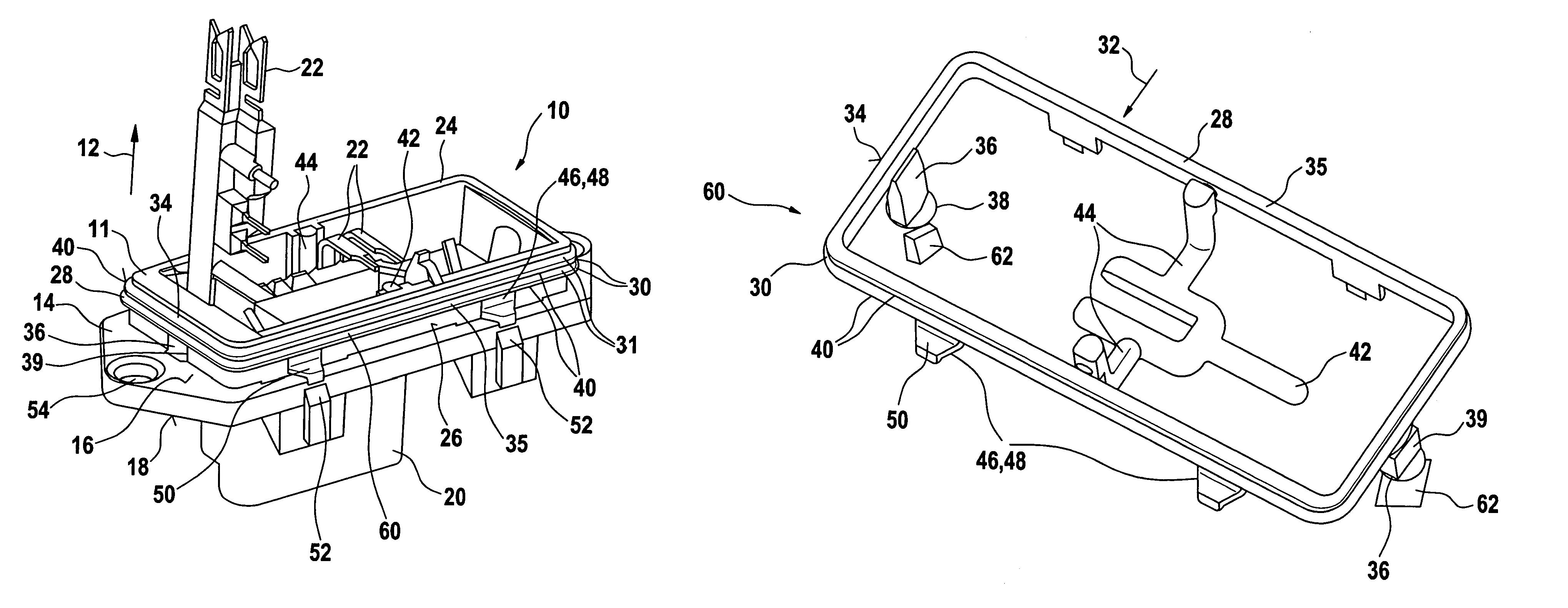
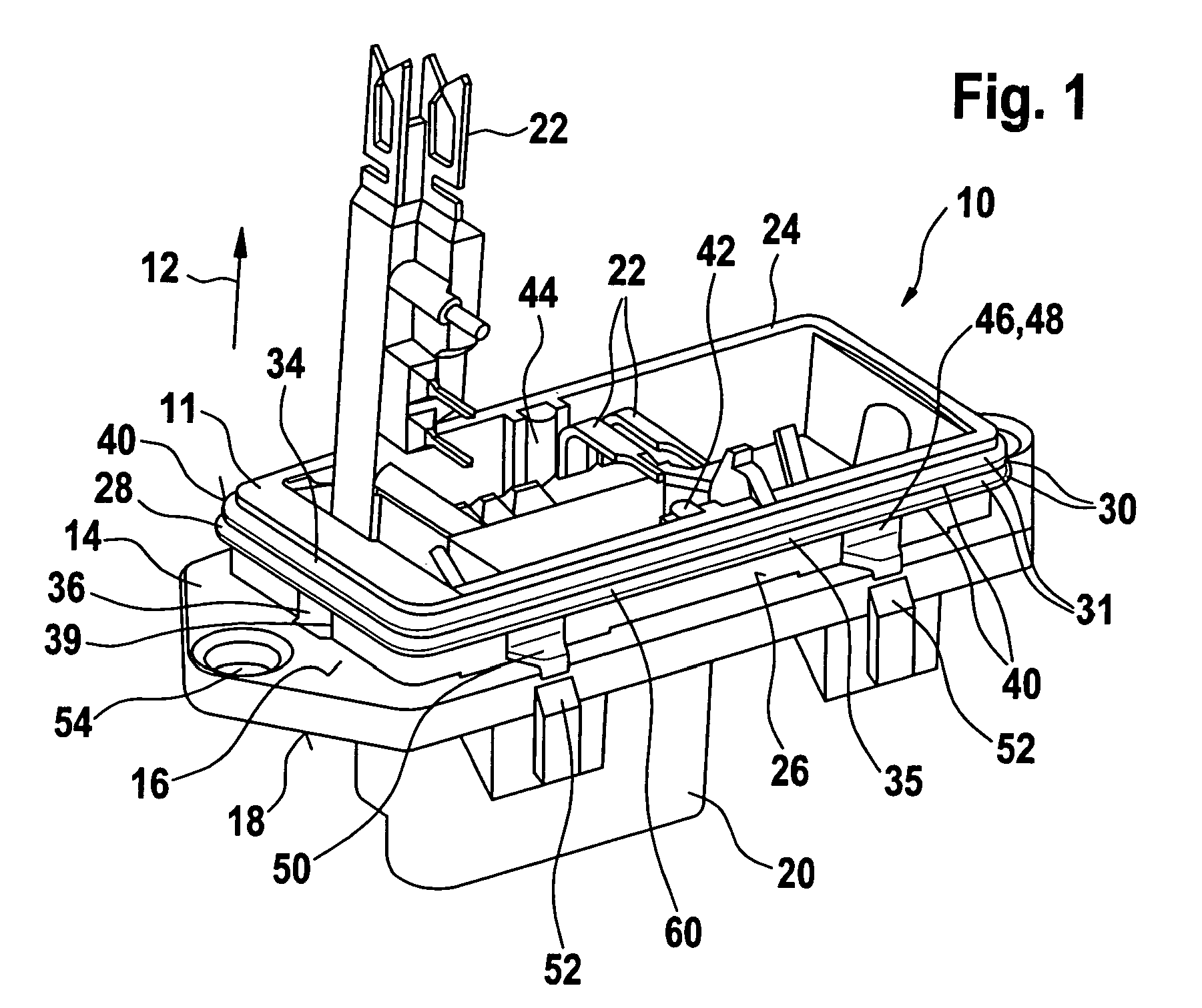
[0018]FIG. 1 shows a housing part 10, which is suitable for sealing a transmission and / or electronics housing of a drive unit in a watertight fashion. The housing of the drive unit, which is not shown in detail, has, for example, an approximately rectangular opening with a radial side wall into which the housing part 10 is inserted in the axial direction 12 to seal the housing shut. The housing part 10 has a cover element 14 with an inside 16 and an outside 18. For example, the outside 18 has a plug connector20 formed onto it and electrical contacts 22 are routed through the cover element 14 to the inside 16. The inside 16 of the cover element 14 has a circumferential wall 24 formed onto it, with a radial outer surface 26 onto which a circumferential radial seal 28 is molded. The radial seal 28 is approximately rectangular, with rounded radii 30 at the corners in order to seal a corresponding rectangular opening in the housing. For example, the radial seal 28 has two or more sealing...


PUM

PropertyMeasurementUnit
surface qualityaaaaaaaaaa
elasticaaaaaaaaaa
volumeaaaaaaaaaa

Abstract

A housing part (10) for a drive unit, as well as a method and mold for manufacturing such a housing part, which housing part (10) is composed of a first component (11) and has a radial seal (28) formed onto it composed of a second, elastic component (60), which has a radial sealing surface (40) for sealing a housing in a watertight fashion; the housing part (10) and radial seal (28) are produced by means of an injection molding process; at least one riser dome (36) is formed onto the radial seal (28) and extends from the radial sealing surface (40) in the axial direction (12).

Description

PRIOR ART[0001]The present invention relates to a housing part for a drive unit as well as a method and injection mold for manufacturing such a housing part, as generically defined by the preambles to the independent claims.[0002]There are many known drive units in which the housing is comprised of various housing parts that are sealed in relation to one another in a watertight fashion for uses in humid environments. For example, DE 200 04 338 U1 has disclosed a power window drive unit in which an insert module can be inserted into a corresponding opening of a transmission housing. In this instance, the insert module represents a housing part that has a cover surface for the opening in the transmission housing, with a plug connector formed onto it. A radial seal with a plurality of sealing lips is formed onto the inside of the housing part and seals the transmission housing upon insertion into an approximately rectangular shaft. Such radial seals are usually injection molded onto th...

Claims


Application Information

Patent Timeline
Patent Type & Authority Patents(United States)
IPC IPC(8): F16J15/02H01R13/64B60J5/04
CPCB29C45/0025B29C45/0046B29C45/1676H02K5/10B29C45/76H01R13/405H01R13/5202H02K7/1166H02K15/14
Inventor MAERKLE, JENS
Owner ROBERT BOSCH GMBH
Why Eureka
Try Eureka