Oil guiding mechanism to avoid oil waste

A technology of oil and oil guide tubes, applied in the field of oil guide tubes, can solve problems such as energy waste, environmental pollution, and waste, and achieve the effects of avoiding oil waste, environmental pollution, and energy waste

Active Publication Date: 2019-05-07
CHENGDU ZHIRONG ZHICHUANG INTPROP MANAGEMENT CO LTD
View PDF5 Cites 0 Cited by
  • Summary
  • Abstract
  • Description
  • Claims
  • Application Information

AI Technical Summary

Problems solved by technology

[0005] The purpose of the present invention is to provide an oil guide mechanism that avoids oil waste, and solves the problem that when a steel oil drum is poured out of oil, after the traditional oil guide pipe completes the oil guide work, a part of oil will still adhere to the inner wall, which cannot be collected and utilized, resulting in a larger Problems of energy waste and environmental pollution

Method used


Image

  • Oil guiding mechanism to avoid oil waste

Examples


Embodiment 1

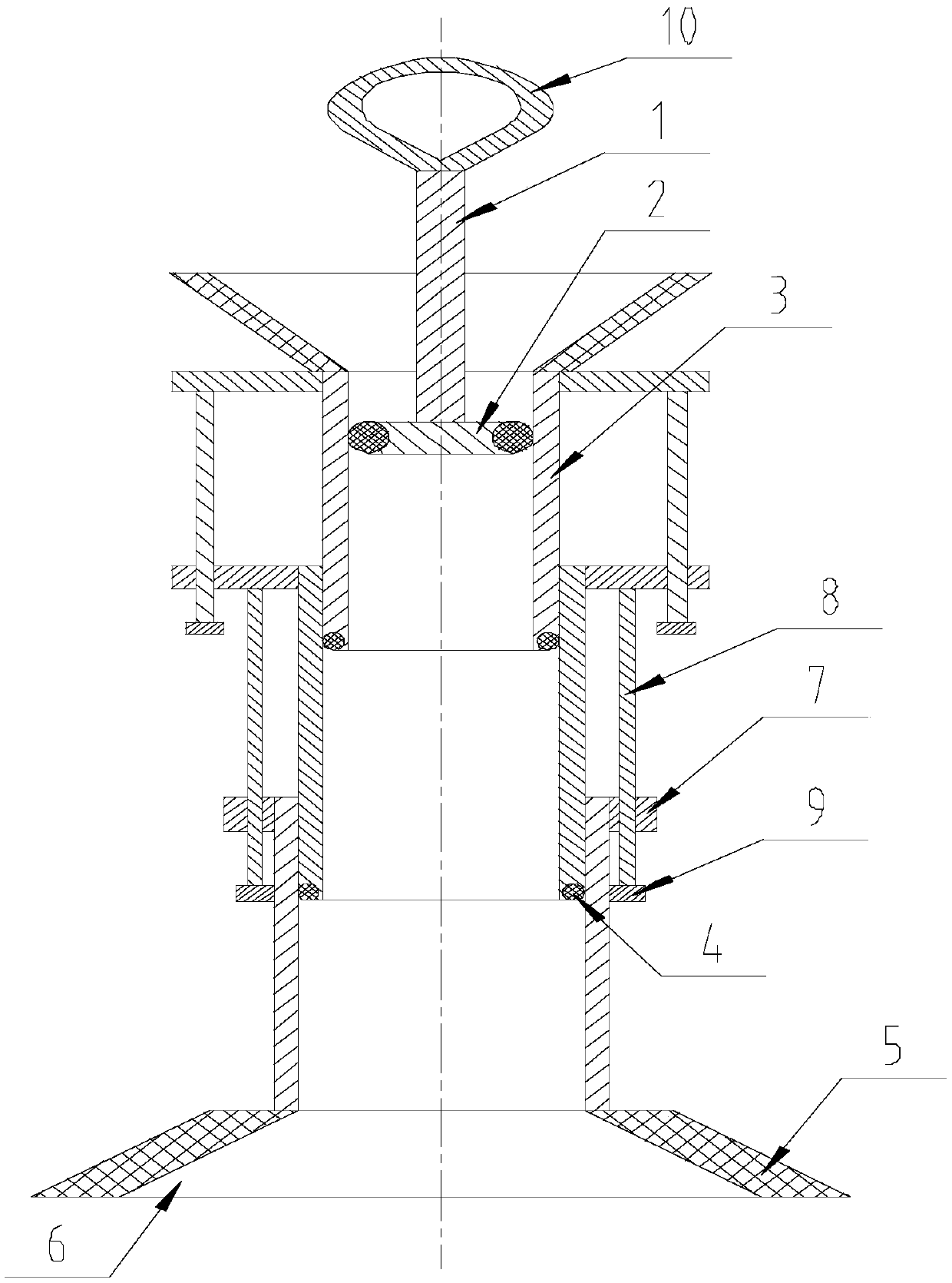
[0028] Such as figure 1 As shown, the oil guide mechanism for avoiding oil waste in the present invention includes a conduit member and a piston rod 1, and the conduit member includes several oil guide cylinders 3 connected in series, both ends of the oil guide cylinder 3 are open, and the guide tubes The outer diameters of the oil cylinders 3 are different, and the inner diameters of the oil guide cylinders 3 are different. Between the oil cylinders 3: one end of the oil guide cylinder 3 with a smaller outer diameter is located in the center hole of another oil guide cylinder 3 with a larger outer diameter, and the outer diameter of the oil guide cylinder 3 with a smaller outer diameter It is consistent with the inner diameter of the oil guide cylinder 3 with a larger outer diameter, and the outer wall of the previous oil guide cylinder 3 is in seamless contact with the center hole wall of the next oil guide cylinder 3;

[0029] A piston 2 is arranged at one end of the pisto...

Embodiment 2

[0032] The present invention is based on embodiment 1, and the present invention is further described.

[0033] Such as figure 1 As shown, in the oil guiding mechanism for avoiding oil waste in the present invention, a sealing ring 4 is provided on the side wall of the oil guiding cylinder 3 at one end of the center hole of another oil guiding cylinder 3, and the sealing ring 4 is an O-ring. The setting of the sealing ring 4 increases the sealing performance between the adjacent oil guiding cylinders 3 .

[0034] Further, suction cups 5 are provided at both ends of the conduit member, and flow guide holes 6 are provided on the suction cups 5 , and the flow guide holes 6 are coaxial with the oil guide cylinder 3 . The suction cup 5 increases the tightness of the joint between the conduit member and the oil barrel or the device for collecting oil.

[0035]Further, the diversion hole 6 is a tapered hole, its small diameter end is close to the oil guide cylinder 3, and its large...

Embodiment 3

[0037] The present invention is based on embodiment 1, and the present invention is further described.

[0038] Such as figure 1 As shown, the oil guide mechanism for avoiding oil waste in the present invention is equipped with a stop ring 7 at one end of the oil guide tube 3, and the axis of the stop ring 7 is collinear with the axis of the oil guide tube 3;

[0039] A limit hole is set on the limit ring 7, the limit hole is a through hole, and its axis is parallel to the axis of the oil guide cylinder 3;

[0040] Among the adjacent oil guide cylinders 3, a limit rod 8 is arranged on the limit ring 7 on the oil guide cylinder 3 with a smaller outer diameter near the other end of the oil guide cylinder 3 with a larger outer diameter. The axis of the limit rod 8 is parallel to the axis of the oil guide cylinder 3;

[0041] In the adjacent oil guide cylinder 3, the limit rod 8 on the limit ring 7 on the oil guide cylinder 3 with a smaller outer diameter and the limit ring 7 on...


PUM


Abstract

The invention discloses a petroleum guiding mechanism capable of avoiding petroleum waste. The petroleum guiding mechanism capable of avoiding petroleum waste comprises a guide pipe piece and a piston rod. The guide pipe piece comprises a plurality of petroleum guide cylinders which are connected in series. The petroleum guide cylinders are sequentially arranged from small to large along the axis according to the outer diameter and the inner diameter. According to every two adjacent petroleum guide cylinders, one end of the petroleum guide cylinder with the small outer diameter is located in a center hole of the petroleum guide cylinder with the large outer diameter. A piston is arranged at one end of the piston rod. The piston is matched with the center hole of the petroleum guide cylinder with the minimum inner diameter. The petroleum guide cylinders are sequentially moved along the axis, so that the guide pipe piece is drawn in, each petroleum guide cylinder with the small outer diameter scrapes off petroleum attached to the inner wall of the corresponding petroleum guide cylinder with the large outer diameter and pushes the petroleum to be accumulated, then the piston rod is used for pushing the petroleum attached to the inner wall of the petroleum guide cylinder with the minimum inner diameter to be accumulated, and the petroleum drops into a device for collecting the petroleum. In this way, the petroleum in the petroleum guide pipe is collected, and energy waste and environmental pollution are avoided.

Description

technical field [0001] The invention relates to an oil guide pipe, in particular to an oil guide mechanism for avoiding oil waste. Background technique [0002] The main components of crude oil are: oily (this is its main component), colloid (a viscous semi-solid substance), asphaltene (dark brown or black brittle solid substance), carbonaceous (a non-hydrocarbon) . Petroleum is a colored, flammable oily liquid with a special smell, mainly composed of hydrocarbons. Natural gas is a colorless, flammable mixed gas with a special odor composed of gaseous hydrocarbon-based gases. The division of labor in the entire petroleum system is relatively fine: the chemical substances that make up petroleum can be decomposed by distillation. As processed products, crude oil includes kerosene, benzene, gasoline, paraffin, asphalt, etc. Strictly speaking, petroleum is mainly composed of hydrocarbons composed of hydrogen and carbon. The four hydrocarbons with the smallest molecular weig...

Claims


Application Information

Patent Timeline
Patent Type & Authority Patents(China)
IPC IPC(8): F16L41/08F16L27/12B08B9/043
CPCB08B9/043F16L27/12F16L41/08
Inventor 贺昶明
Owner CHENGDU ZHIRONG ZHICHUANG INTPROP MANAGEMENT CO LTD
Why Eureka
Try Eureka