Composite structure for high efficiency hydrogen separation containing preformed nano-particles in a bonded layer

Inactive Publication Date: 2010-07-06
POWER & ENERGY
View PDF13 Cites 11 Cited by
  • Summary
  • Abstract
  • Description
  • Claims
  • Application Information

AI Technical Summary

Benefits of technology

[0022]Regardless of its method of construction, the porous layer of hydrogen permeable material supports the solid layer and enables the solid layer to withstand large pressure differentials. Furthermore, the porous layer of the hydrogen permeabl

Problems solved by technology

However, in many common processes that produce hydrogen, the hydrogen gas produced is not pure.
Rather, when hydrogen is produced, the resultant gas is often contaminated with water vapor, hydrocarbons and/or other contaminants.
However, palladium is a very expensive precious metal.
Consequently, conduits made of palladium and palladium alloys are very expensive to manufacture.
Furthermore, conduits made from palladium and palladium alloys typically hold gas under pressure and at high temperatures.
Accordingly, the walls of the conduit cannot be made too thin, else the conduit will either rupture or collapse depending on the pressure gradient present across the wall of the conduit.
However, as has already been stated, a conduit wall cannot be made so thin that it ruptures or collapses under the pressure of the gases being passed through that conduit.
To further complicate matters, conduits made from palladium and palladium alloys may become less efficient over time as the interior walls of the conduits become clogged with contaminants.
However, when such conduits are cleaned and the external pressure of the conduit is raised higher than the interior pressure, a much lower pressure gradient must be used, else the conduit will implode.
However, the conduit is incapable of holding the same pressure gradient as solid palladium conduits.
A problem associated with such prior art systems is that the palladium or palladium alloy membrane is typically positioned in a level plane, wherein a pressure gradient exists from one side of the m

Method used


Image

  • Composite structure for high efficiency hydrogen separation containing preformed nano-particles in a bonded layer
  • Composite structure for high efficiency hydrogen separation containing preformed nano-particles in a bonded layer
  • Composite structure for high efficiency hydrogen separation containing preformed nano-particles in a bonded layer

Examples


Example

DETAILED DESCRIPTION OF THE DRAWINGS

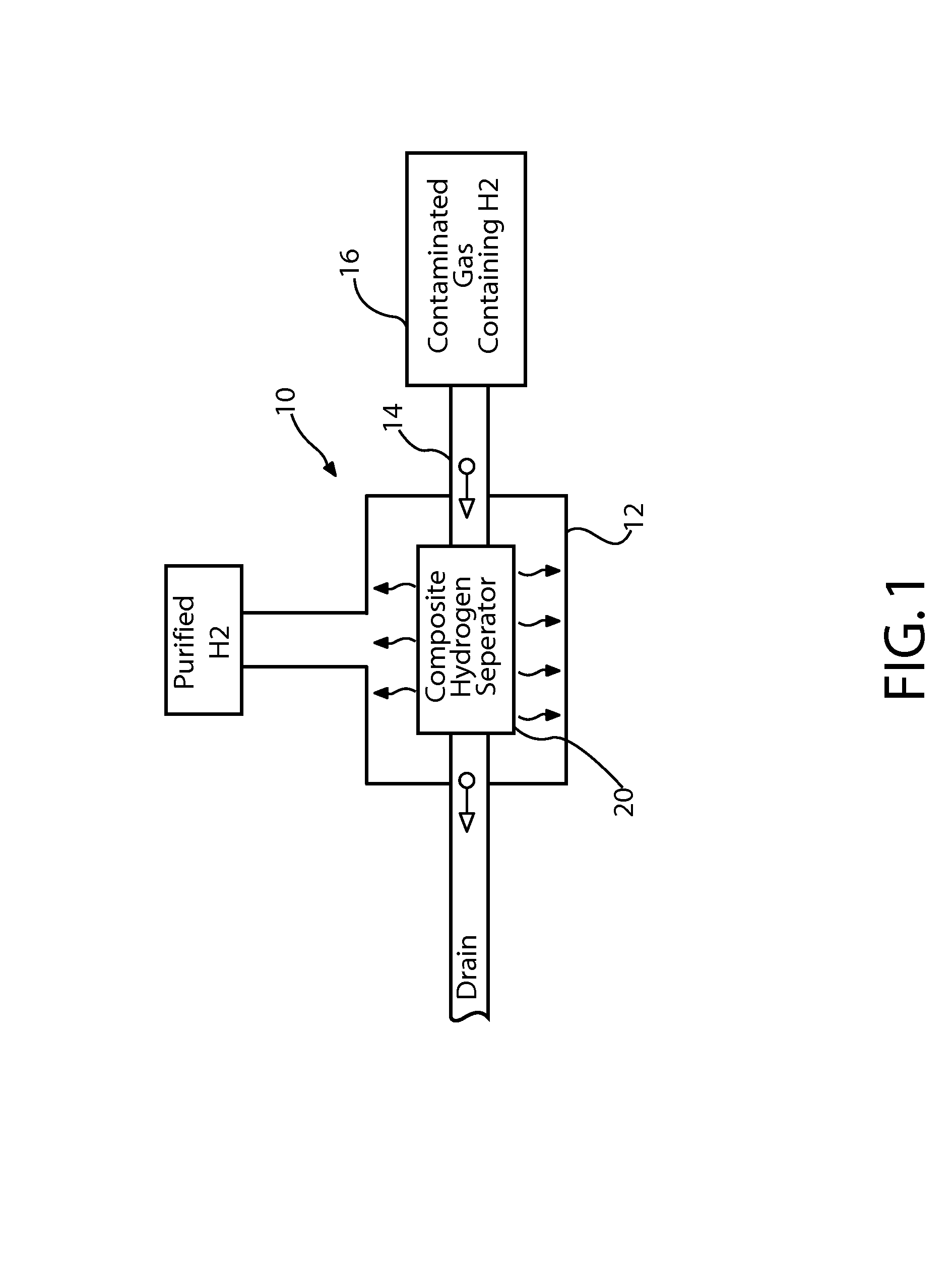
[0035]The present invention system provides a means for purifying a hydrogen gas at a high flow rate, using a small amount of space and a small amount of precious metals.

[0036]Referring to FIG. 1, there is shown a schematic of an exemplary embodiment of a hydrogen purification system 10 in accordance with the present invention. The hydrogen purification system 10 contains a collection chamber 12 for collecting purified hydrogen gas. At least one supply conduit 14 extends into the collection chamber 12 where each of the supply conduits 14 is coupled to a source of contaminated hydrogen gas 16. The supply conduit 14 is mostly fabricated from stainless steel or an equivalent alloy that is capable of retaining the contaminated hydrogen gas at a first pressure and at a predetermined operating temperature of at least three hundred degrees centigrade.

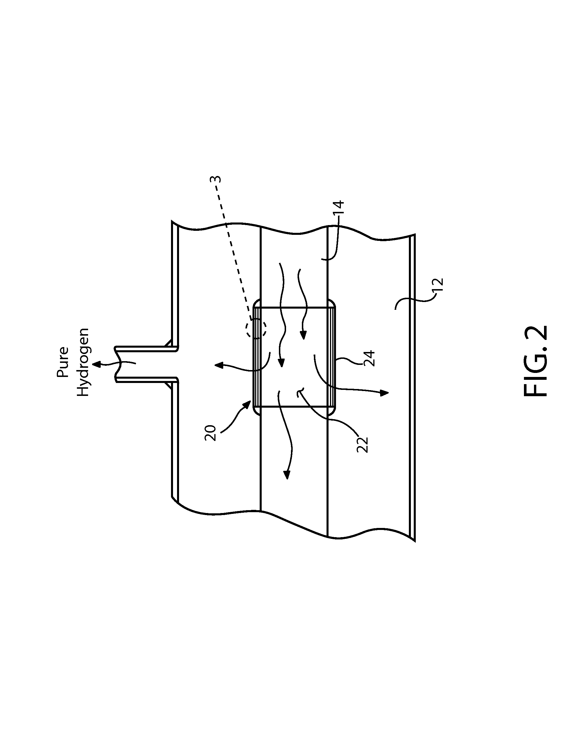
[0037]Along the supply conduit 14 is disposed a composite hydrogen separator 20. The composite hydrogen s...


PUM


Abstract

A hydrogen purification system and method that utilizes a hydrogen separator with a novel composite structure. The hydrogen separator has a first porous layer of a hydrogen permeable material. The first porous layer is comprised of premanufactured nano-particles of hydrogen permeable material that have been bonded together. A solid layer of the same hydrogen permeable material is then disposed onto the first porous layer. A pressure differential is created across the structure of the composite hydrogen separator. The porous layer of hydrogen permeable material supports the solid layer and enables the solid layer to withstand large pressure differentials. Furthermore, the porous layer of the hydrogen permeable material bonds to the solid layer, thereby greatly increasing the effective surface area of the solid layer that is exposed to hydrogen gas. Accordingly, a large flow rate of hydrogen gas can be obtained in a small amount of space.

Description

RELATED APPLICATIONS[0001]This application is a continuation-in-part of application No, 10 / 770,732 filed Feb. 2, 2004 now U.S. Pat. No. 7,125,440, also entitled Composite Structure For High Efficiency Hydrogen Separation And Its Associated Methods Of Manufacture And Use, which claimed priority of Provisional Patent Application No. 60 / 475,620 entitled Composite Nano-Structure For High Efficiency Hydrogen Separation, which was executed on Jun. 4, 2003.BACKGROUND OF THE INVENTION[0002]1. Field of the Invention[0003]The present invention relates to systems and methods that are used to separate molecular hydrogen from a volume of gas. More particularly, the present invention is related to systems and methods that separate hydrogen from a volume of mixed gas by exposing the mixed gas to a hydrogen permeable material through which only atomic hydrogen can readily pass.[0004]2. Description of the Prior Art[0005]In industry there are many applications for the use of molecular hydrogen. Howev...

Claims


Application Information

Patent Timeline
IPC IPC(8): B01D59/12
CPCB01D53/228B01D69/12B01D71/022C01B3/503C01B3/505B01D2256/16C01B2203/0405B01D69/1216B01D71/02232
Inventor BOSSARD, PETER R.METTES, JACQUES
Owner POWER & ENERGY
Why Eureka
Try Eureka